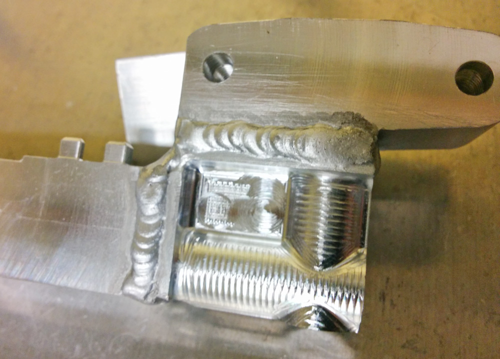
As mentioned in the last post, now that the injectors are mounted in the fuel rail and there are no leaks, it’s possible to measure the injector performance.
A fuel injector is essentially a very fast-acting and well calibrated valve. It has an electromagnetically actuated plunger that opens when current flows through the solenoid, letting fuel flow at a precisely calibrated rate, and closes when the current is turned off.
At least that’s the idea. In practice, of course, it’s not that simple. It’s a mechanical device and hence is bound by the laws of physics. When a voltage is applied to the injector, it takes a finite amount of time for current to build up and for the magnetic field to start pulling the plunger. The plunger then has to travel a finite distance during which the valve is only partially open. Once fully open, the flow rate through the injector depends on the fuel pressure and on the manufacturing tolerances of the orifice that lets the fluid through. Then when the voltage is turned off, the same thing happens in reverse; it takes a finite (but smaller) time for the plunger to return to the closed position.
The end result is that while an ideal injector delivers a fuel mass m = r * t, where r is the mass flow rate of the injector, in the real world there is a “dead time” such that if you send an electric pulse of time t, the valve is actually open for a smaller time t – dt, where dt is the “dead time” of the injector. On top of that linear model, there are additional effects for short opening times due to the fact that the injector then is partially open for a significant fraction of the pulse, but the simplest useful description of a fuel injector’s performance is
m = r * (t – dt)
Oh, but there’s more. Since the dead time depends on how hard the electromagnet is pulling the plunger, it depends on the voltage applied to the injector. This means that at very low voltages, like when you’re trying to start the engine, you need to apply longer pulses to get the same amount of fuel.
So there’s a lot of information you need to capture in order to know how a fuel injector performs. Remember that any mismatch between how much fuel the engine controller thinks that it’s delivering and how much is actually delivered will show up as a deviation in the fuel/air ratio. If you don’t have a good description of the injector, that fact will feed back into your assumptions for how much air you think the engine is pumping and will make the tuning harder and less predictable. And if the injector to the different cylinders don’t deliver the same amount of fuel, it’ll be impossible to get all the cylinders to run at the correct air/fuel ratio.
If you have an unlimited budget, you can buy injectors from places like Injector Dynamics, that measure and match sets of injectors that perform very similarly. I don’t have an unlimited budget (although sometimes I wonder if that’s true in practice) and even if I did, they don’t sell them for 100cc cylinders that make 15hp. 1000cc cylinders that make 150hp is more like their target market…
When I tried to find injectors, I browsed the awesome collection of injector data collected by Stan Weiss and looked for ones that would have a suitable flow rate. The fuel flow rate needed is only determined by two things: the maximum amount of power the cylinder makes, and the air/fuel ratio it runs at. Since sportbikes have very high horsepower for a given displacement (since they are usually very high revving engines) they actually need higher flow rates than you might think given how small the engine is.
Since the NC30 makes ballpark 60hp, i.e. 15hp per cylinder, the required injector size comes out to be about 85-110 cc/min, depending a bit on the air/fuel ratio and the margin you want. Since gasoline has a density of about 0.72kg/l, this corresponds to about 60-80 g/min of fuel.
Alternatively, you can do the a simple calculation without any assumptions at all: At an RPM of 12,000 (power peak), a 100cc cylinder pumps 6000*0.1 = 600 l of air per minute. Air has a density of 1.2 g/l, so that corresponds to 720g/min. If we want to run at a lambda of 0.85 at full throttle, that corresponds to an air/fuel mass ratio of 14.7*0.85, so that comes out to be 720g/min/(14.7*0.85) = 57g/min. However, you don’t want to run the injectors at full duty cycle. If we demand a maximum duty cycle of 80%, we need injectors that flow 72g/min of fuel. (It’ll actually be a bit less than that because the volumetric efficiency is less than 100%, so each engine cycle doesn’t pump the full 100cc of air.)
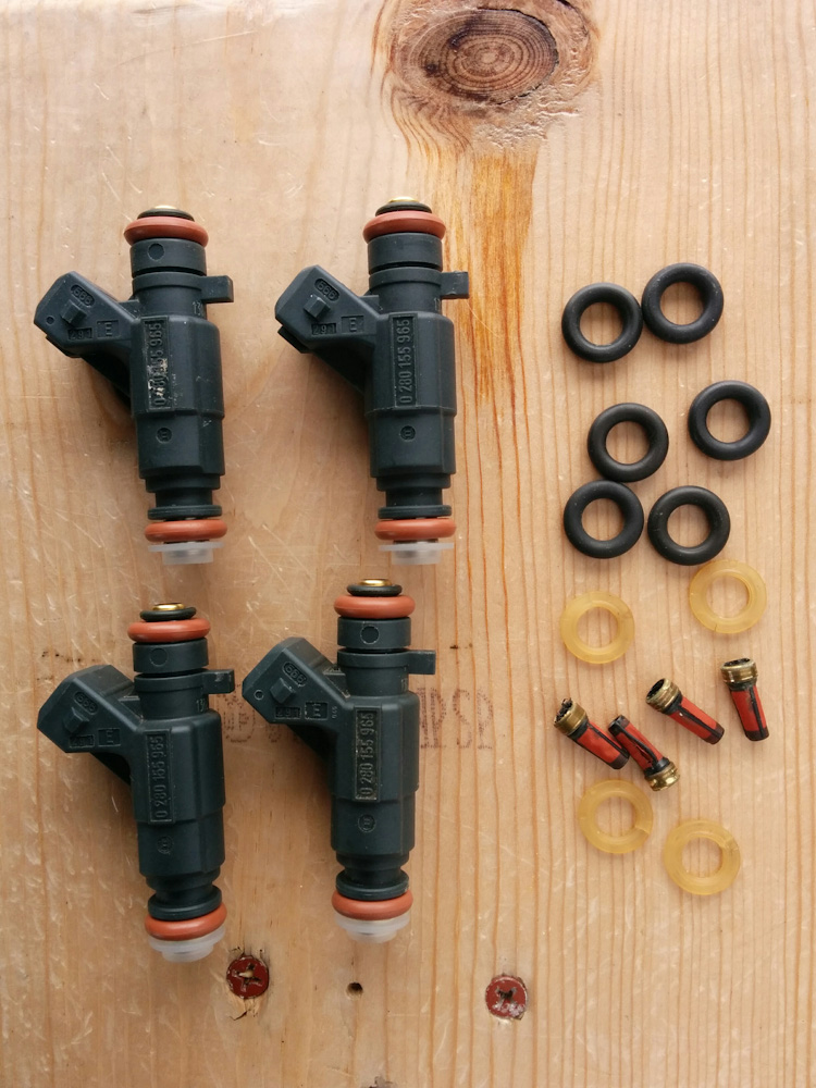
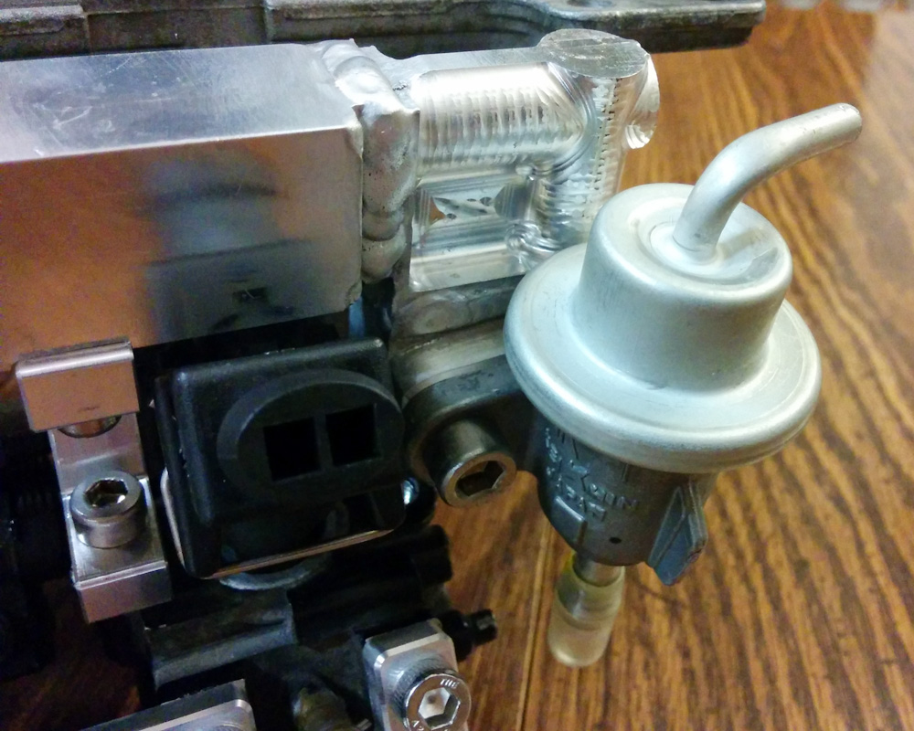
Scanning through that very large table there are a few injectors with flow rates in the correct ball park, and after also searching for the corresponding model numbers on ebay, I hit upon the Bosh 0-280-155-965 (used in a 1.2L Opel engine) which has a posted flow rate of 68g/min and ordered a used set of those. That was a year ago, and it’s not until now that I can verify whether those injectors actually are going to do what they are supposed to.
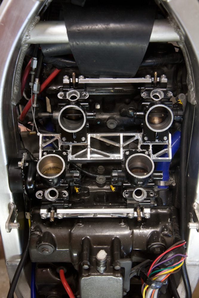
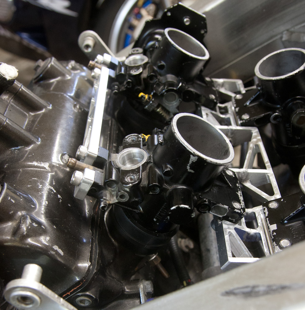
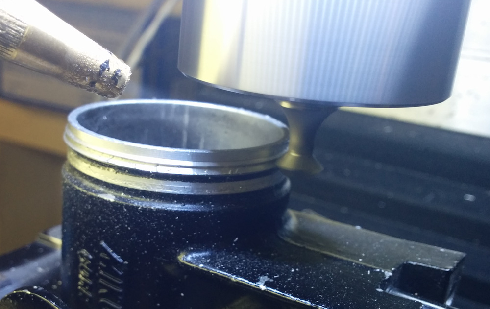
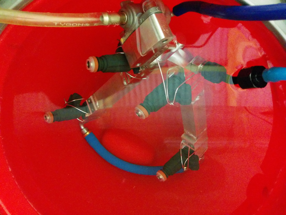
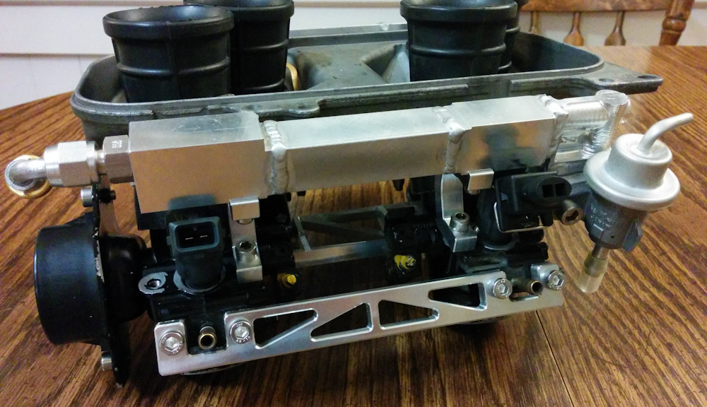
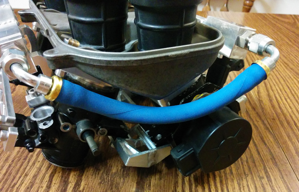
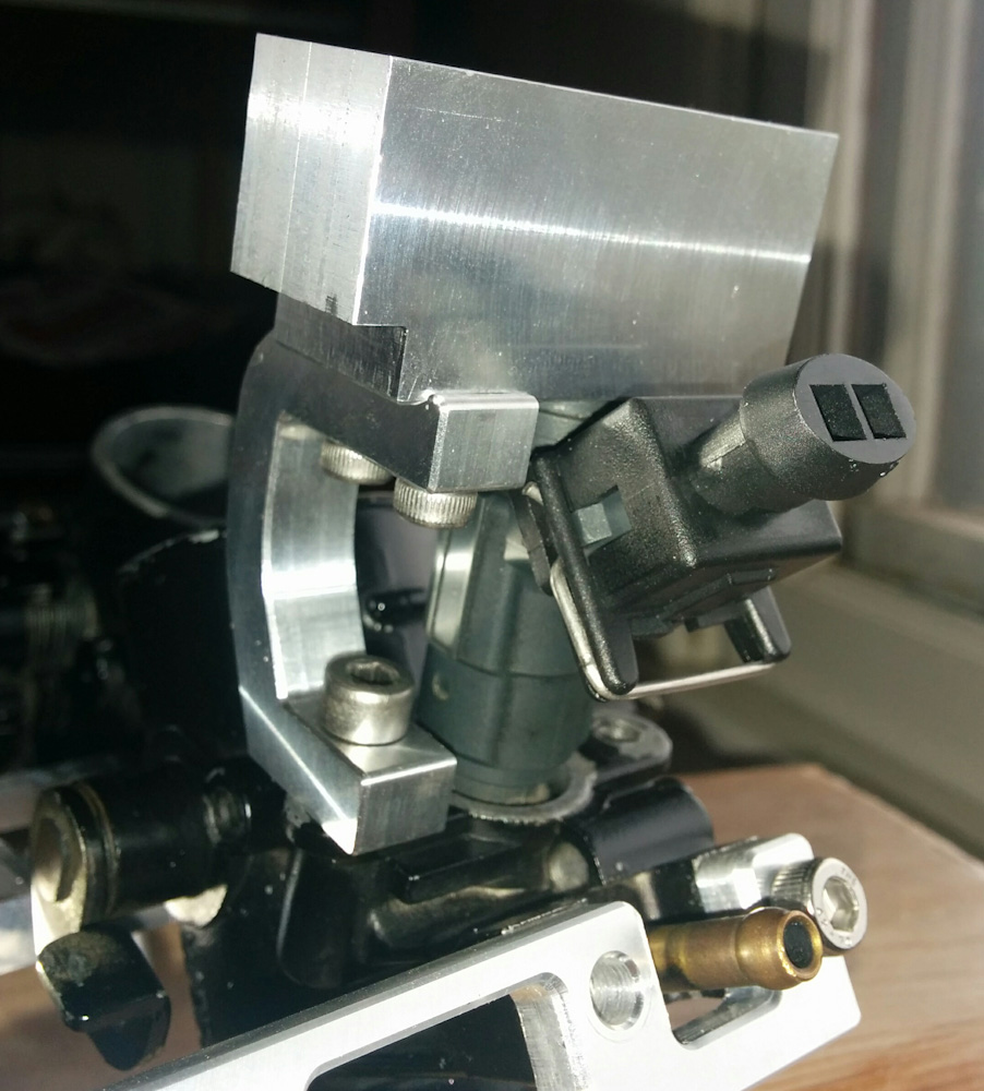
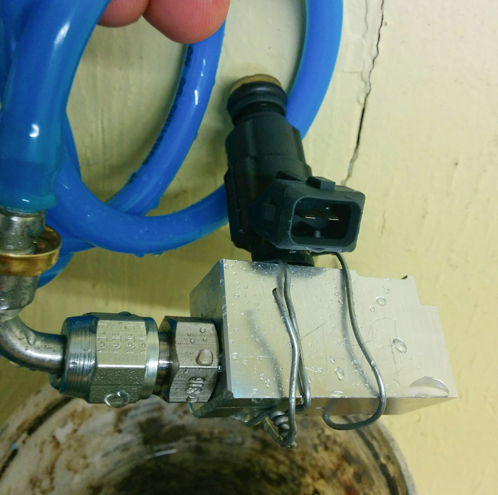
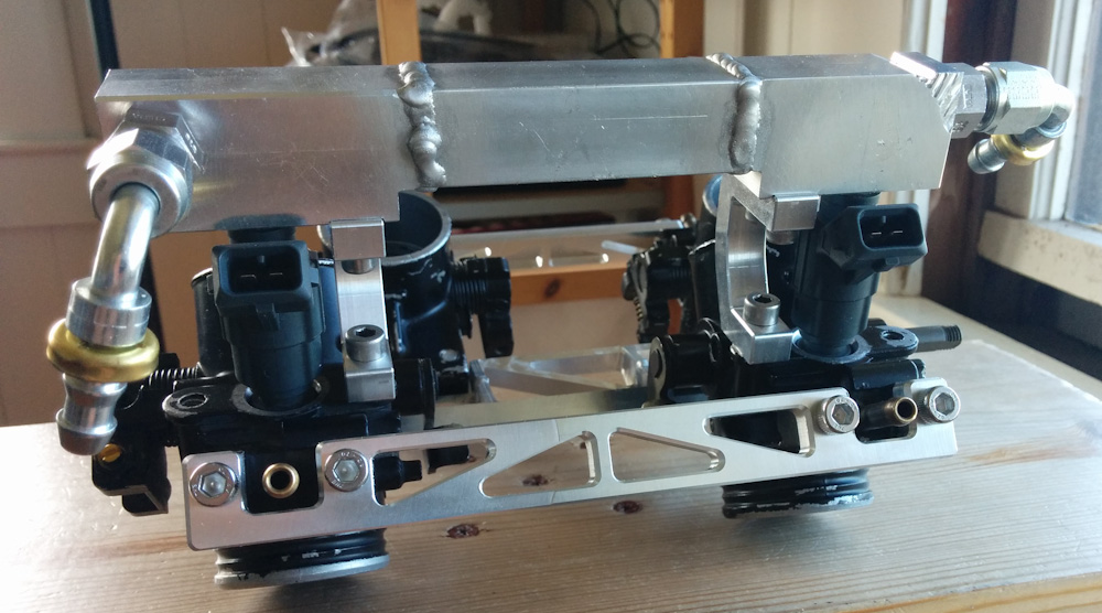
To test this, I took the assembled fuel rail and throttle bodies, connected up the fuel pump and filter, and pumped gas from a gas can. The injector is hooked up to the Microsquirt, and in test mode you can tell it to fire the injector for a specified number of times for a specified length. Then I measured the resulting mass of fuel on my 0.01g resolution scale.
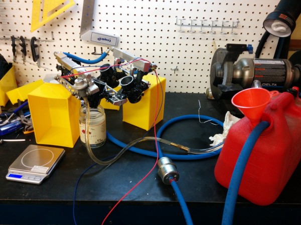
The injector test setup. Fuel from a set number of injections is meterd into a glass jar, and the mass of fuel injected measured with my very sensitive 0.01g scale.
I have to point out that this is a somewhat sketchy operation. The fuel injectors don’t just dribble liquid into the jar, they atomize the fuel and a significant part of it gets into the air. I had the garage door open, the fire extinguisher standing by, and wore a respirator the whole time since the garage positively stank of gasoline.
To get enough mass of fuel to reliably measure it, I pulsed the the injectors anything from 250 times to 3000 times (for short injection times.) This resulted in 5-10g of fuel in the jar, easily measured on the scale. Being a good experimental physicist, all measurements were repeated 3 times to get an estimate of the variance.
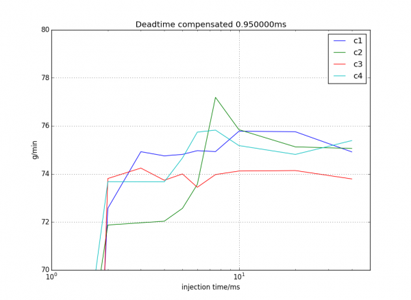
This plot shows effective mass flow rate for each of the injectors after accounting for dead time. My best estimate of dead time is 0.95ms.
The result is shown in the plot above. This is a slightly processed plot, in that the quantity plotted is (fuel mass)/(injector pulse time – dead time), which allows you to estimate the dead time. If your estimate of dead time is correct, the curves will be mostly horizontal. Now, they aren’t exactly horizontal, since the injectors aren’t perfectly linear. My estimated dead time is 0.95ms, but at times less than 2ms, the curves drop like a stone. This is an indication that the injector doesn’t have time to open completely in that time.
For times longer than 2ms, though, the behavior looks pretty good except for the cylinder 2 injector in green. I think this is an experimental artifact. In the interest of taking the measurements as fast as possible, I initially only waited a very small time between each injection, like maybe a 7.5ms injection pulse every 10ms. This seems to overestimate the flow rate, maybe because the fluid flow through the injector never really has time to come to a complete stop. For the other cylinders I decided to wait at least as long as the injection pulse, and never less than 20ms, between each injection. Those curves look more linear, so I’m going to redo the cylinder 2 measurements, too.
The other thing to note is that the flow rate is more like 75g/min, not 68. However, the 68 is specified for 3bar fuel pressure, and my fuel pressure regulator apparently is set more like 3.5bar. The flow rate through an injector goes as the square root of the pressure, so taking 68*sqrt(3.5/3) gives you 73g/min. Close enough for me.
Another thing that stands out is that the cylinder 3 injector, in red, flows less than the three others by about 1.5%. This is a bit suboptimal, because it means one cylinder will run leaner than the other. (If two injectors were lower, I could put those on the same cylinder bank and tune those to be on a bit longer, but the Microsquirt only has 2 injector outputs so they have to be wired two and two.) However, a lambda error of 1.5% isn’t bad, I don’t think that will dominate the air/fuel ratio error.
I still have to measure how the dead time depends on voltage. That means repeating this exercise for a bunch of different voltages (this was at a voltage of 12.9V as read by the Microsquirt), but I think I’m just going to assume that all four behave similarly in this aspect and just measure one of them. But that’ll be the topic of a future post.