My computer’s graphics card (an ATI 5870 from 2010) finally died, the monitors started going black after a few minutes of use. Time to get a new one, I guess. The only hitch is that my computer is water cooled (there’s a page describing this project on my old, now-defunct online photo album) so a new card meant that the water blocks potentially wouldn’t fit. But: I have a CNC mill, there are no obstacles that can’t be overcome.
When the new card arrived, I quickly determined that while the main GPU water block would work fine. The one cooling the voltage regulators, though, would not fit. That’s not a big problem, though, I would just have to mill out an aluminum adapter of suitable shape that it would touch the voltage regulators and be screwed into the holes on the PCB. The water block that has coolant running through it would then be bolted to this adapter.
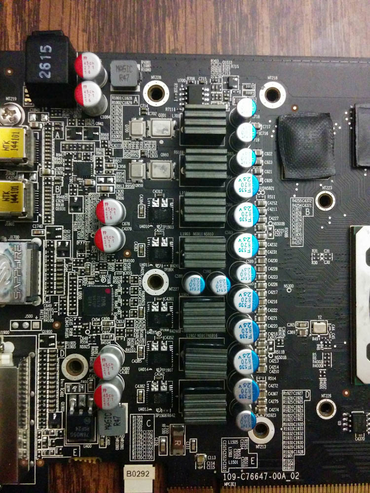
The vertical row of small ICs are the voltage regulators. The large shunt resistors to the right of them were also cooled by the factory fan.
I took some measurements and designed an aluminum piece that would bolt to the two holes in-line with the VRMs and to the extra hole on the left to get more stability. Some silicone thermal pads would provide the required cushioning to get good contact to both the VRM chips and the shunt resistors.
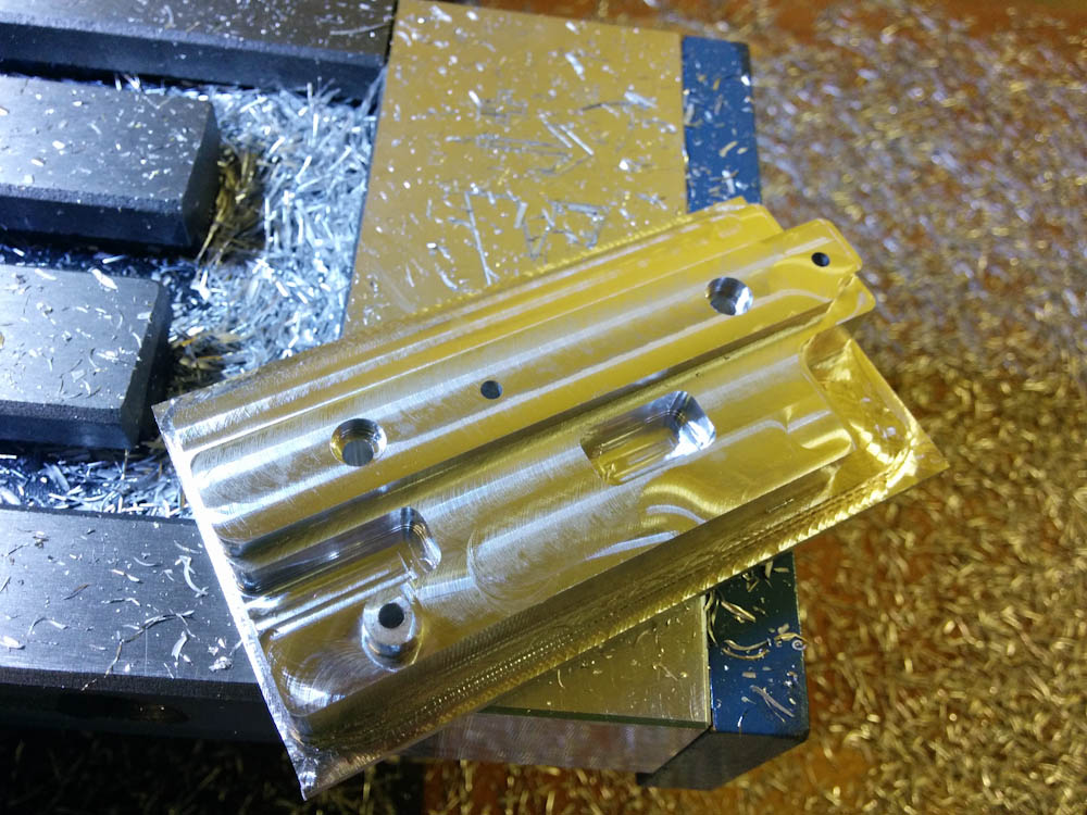
Here’s the bottom side of the water block after milling. The highest part is where the VRMs are. The two large screw holes are for bolting the actual water block, that provides the cooling, to the other side of this piece.
This was the first “production” milling project, and it went fairly well. I did experience some chatter on the full-length cuts around the perimeter. I’ll write a separate post about hunting this down. The only other issue was that I made the counterbores for the two hex head screws for the water block too small. It turns out that screws heads, at least the ones you buy at Home Depot, are noticeably off-center from the screw axis. I had measured the heads to get them to fit, but I had to add about half a millimeter of clearance before they would actually turn.
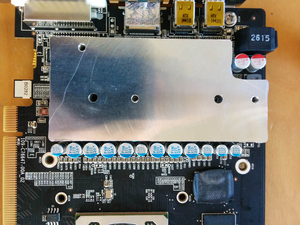
The adapter in place for test fitting. It was a bit tight, but works fine. This is a test fit, because the water block has to be screwed in from the bottom before mounting the whole thing to the PCB. The uneven edges on the top are from manually deburring the edge resulting from not milling far enough down. I have since come to appreciate the awesomeness of chamfer mills!
This little project was a success! I can’t measure the VRM temperatures, but the aluminum block certainly gets warm when the graphics card gets busy, so there is heat flowing into it. These analog components tolerate quite high temperatures, so the actual temperature isn’t much of an issue as long as there’s something conducting the heat away.