The last post described how the injectors mount into the throttle bodies. The next step was was to get fuel to their upper parts. This is commonly done by using a “fuel rail”, in which fuel is pumped past the injectors, to the fuel pressure regulator, and then returns back to the tank. By having fuel constantly circling past the injectors any air in that space is returned to the tank. This makes it easier to prime the system. Another advantage is that fuel doesn’t hang around near the engine, getting heated up and possibly boiling. Boiling fuel is bad, since it means the injectors aren’t fed liquid fuel any more. (The high fuel pressure used in fuel injection systems makes this pretty unlikely compared to a carbureted engine, though.)
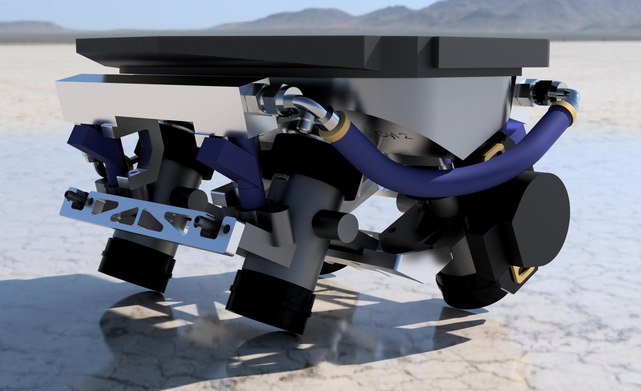
This Fusion360 rendering of the throttle bodies shows the design of the fuel rail. There is a custom-designed part for each injector, containing the mounting hole for the injector as well as an AN-4 O-ring port for the inlets and outlets, as well as the attachment for the brackets holding the rail to the throttle bodies.
Since it is a “V” engine, the front and rear cylinders have their own fuel rails, that must be connected to each other with coupling hoses. As usual, coming up with a design that fit in the available space took a few iterations. The 90-degree hose fittings are long enough that they needed to fit quite near to the injectors to not run into the frame rails, especially on the “outer” cylinders (1 and 4). To make it compact enough, the hole for the injector, the threaded port where the AN fitting attaches, and the mounting holes for the “U”-shaped brackets that hold the fuel rails to the throttle bodies are machined out of a single piece. The two pieces for the front and back cylinders, respectively, are then connected to each other with a short piece of 3/4″ square tubing and welded together. This should (hopefully) make a leak-proof, all-metal part that simultaneously holds the injectors and the AN-4 fuel connections.
These pieces are a bit complicated to make, since they require machining on 3 sides. I started by making a proof-of-concept part to make sure that I could actually machine the injector and AN connections without getting any leaks. The AN connection, more precisely known as a “SAE J1926-1 straight thread O-ring port”, in particular has a “cone” in the opening for the O-ring to fit, which supposedly needs to have quite exact dimensions to get the correct amount of compression of the O-ring. Before I went along and made up the entire thing, I wanted to make sure that part would work.
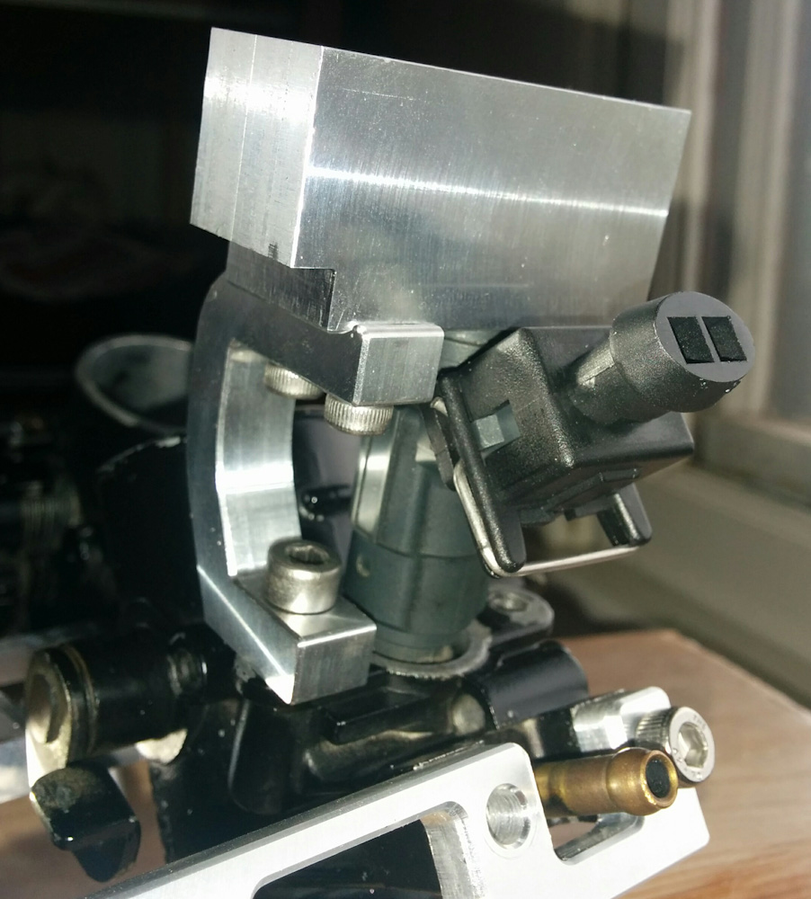
This is the proof-of-concept fuel rail piece, mounted on the bracket and holding the injector. The opening on the left side was deliberately omitted so the other connections could be checked for leaks.
The first part was actually mis-machined, the X-axis lost steps during the operation so the holes, which were drilled first, were a bit off-center. (I think I was too aggressive when cutting the hole for the injector. When the pilot hole is only slightly larger than the endmill, the cut starts with very small radius circles, and the contact point moves almost twice as fast as the center of the endmill. If you’re already pushing the feed rate, I guess this effect is enough to push it over the edge. For the real parts, I backed off to 50% feed when cutting the hole and had no further problems.)
Even if the holes were a bit misplaced, I could use the part for leak checking. Since I needed to be able to pressurize the part, I left the opening towards the center, where the square tubing would be welded on, closed off. I could then mount the injector, connect the AN-4 connection to an air hose, and see if there were any leaks.
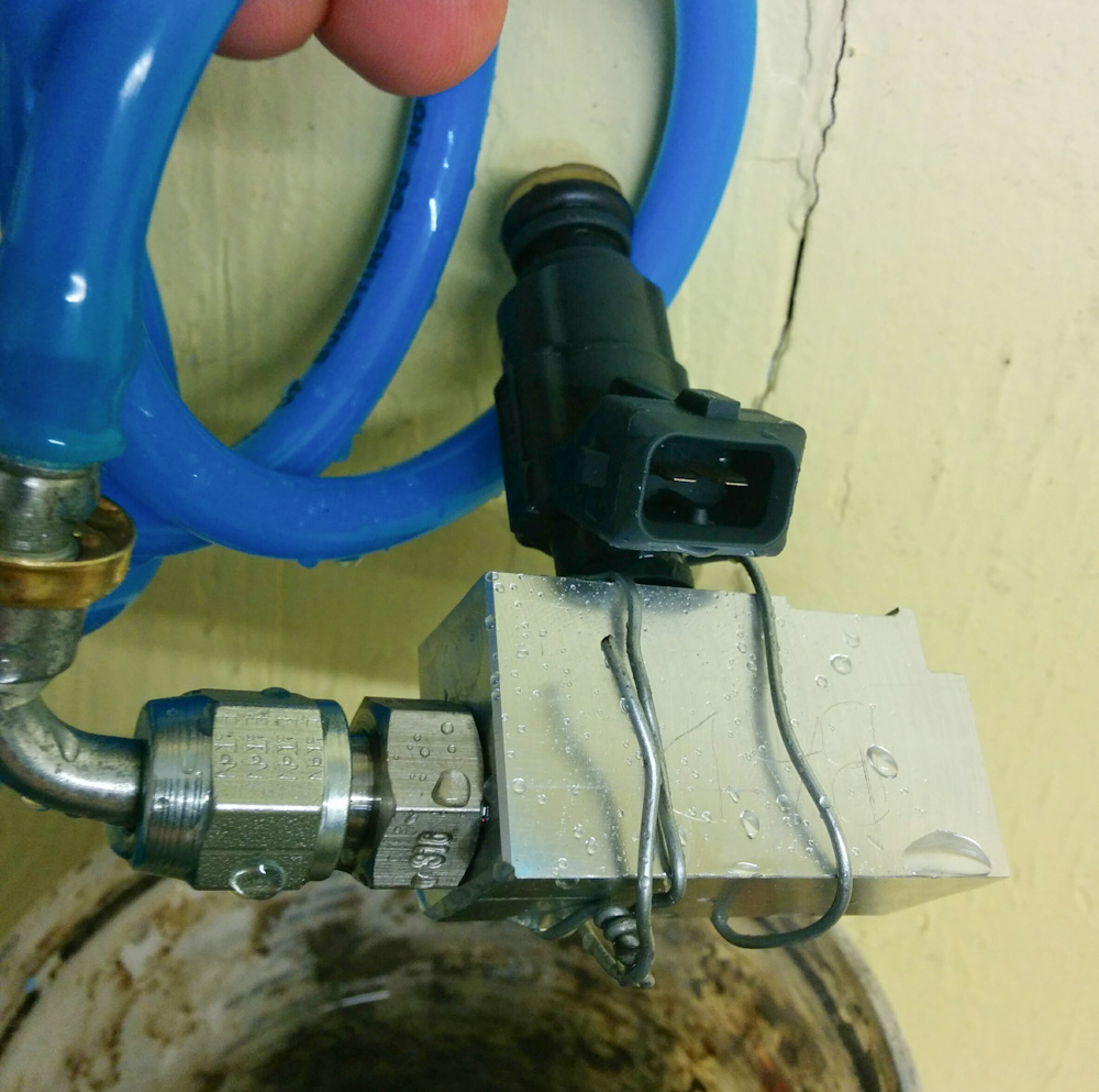
The leak check in action. The injector is held in the hole with some steel wire, and the air hose is connected to the AN-4 elbow screwed into the O-ring port on the left. Pressurizing this to 4 bar and dunking the hole thing in water showed that I had a good seal.
I had to tighten the AN-4 flared connection on the 90-degree elbow a bit tighter than I thought to not have a small air leak, but it’s a steel-to-steel connection and those do need higher seating force to seal than if one of the sides is aluminum. The connections I was worried about, the O-ring where the AN-4 adapter screws into the fuel rail piece and the O-ring on the injector, were perfectly sealed.
While I had the connection pressurized, I tried connecting the injector to 12V to make sure it worked, which it did. I’ll do a real measurement of the flow rate of all four injectors, using gasoline, once everything is mounted. This is needed to calibrate the “dead time”, which is how long the injector needs to be turned on before the flow starts. This quantity is important to get accurate fuel metering for very short pulse widths.
After a few evenings of dedicated mill work, I had three of the four parts of the fuel rail done. (The fourth, for cylinder 3, will mount the fuel pressure regulator and needs some more testing to make sure it will fit.) The side for cylinders 2 and 4, though, was ready for welding.
This was a bit nerve racking, as I haven’t welded much lately and this is a critical weld that must not have any pores, since that will mean a fuel leak. I had a few iffy starts, I have a problem with weld contamination and I don’t know what’s causing it. I get a lot of black deposits around the weld. I’ve double checked the flow rate, which is OK. It’s possible there is a leak in the hose to the torch through which air is sucked in, leading to contamination. It’s also possible the Argon is contaminated; one would hope they would have sufficient quality control but it apparently happens.
In the end, the welds didn’t come out great, there are some that are a bit cold and there’s some contamination, but I’m pretty sure there’s a continuous weld. I can’t pressure test the part until I complete all the connections since it’s now open on both sides, but I’d be surprised if it leaks.
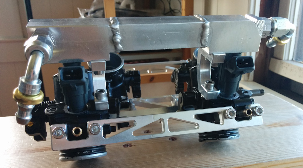
Here it is, the fuel rail for the front cylinders, complete with injectors and AN hose fittings. The left side will be the inlet from the fuel pump and the right side goes to the back cylinders. Things are finally beginning to come together! (If you wonder what the marks are in the top right corner, there was an “incident” when milling that part, it came loose in the vise and got a bit chewed up.)
So that’s half the fuel rail done! It’s satisfying to finally see things come together after so much planning and fiddling trying to get things to fit. The first post for this project was in May 2015, and if I had known it would take a year to get things to come together, I’m not sure I would have started it. It’s getting close now, though.
Pingback: Microsquirting the NC30, part #19: The other fuel rail – Patrik's projects