In the last post, I described the machining of the throttle body adapters. Once those were done, it was time to move along to make some brackets to hold the throttle bodies in position. Since it is a V-4 engine, the two rows of throttle bodies are at an angle to each other. They are nominally held in place by the adapters I discussed in the last post, but since those are circular, they don’t constrain the rotation of the throttle bodies around the intake axis. Those couplings are also slightly flexible, so it would be good to mount them more rigidly to each other.
The GpZ1100 throttle bodies have screw holes for mounting rails along the top and bottom edges. The bottom holes of the ones on the opposite sides of the “V” end up quite close to each other, so I designed a single mounting bracket that would hold all four at the correct angle. The top holes of each row can then be bolted to another bracket, providing further rigidity. Here’s a Fusion360 rendering of the entire assembly:
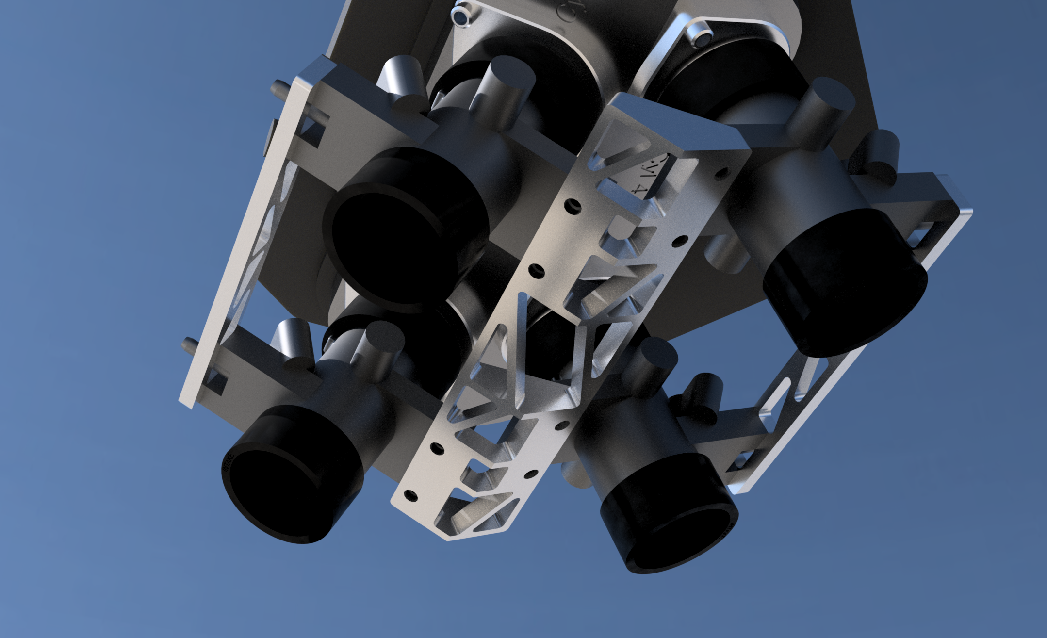
A rendering of the bottom side of the throttle body assembly, showing the three aluminum brackets that hold the throttle bodies in position.
The design of the angled bottom bracket was a perfect example of Fusion360’s “top-to-bottom” design style. I had already modeled the throttle bodies and how they attached to the airbox, so now I could design a bracket that mounted to the bottom screw holes. By mirroring this part across the centerline of the “V”, I then ended up with a part that had the correct angle and spacing to hold the throttle bodies in the right position.
Since this part isn’t flat, it couldn’t be milled in one piece (it could be done with a 4-axis machine… that would be nice…) but since it was modeled as a mirrored design, I could machine each half separately and they would then have the correct shape to be welded together.
Initially I had designed it as just a block of aluminum, but I figured I should leverage the power of Fusion360 and get rid of unnecessary material. The final bracket, as can be seen above, has much less material. Time to manufacture. I’ll let the pictures speak for themselves.
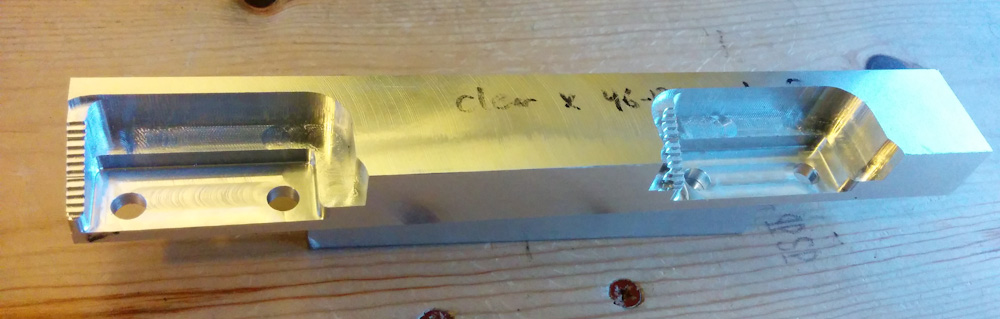
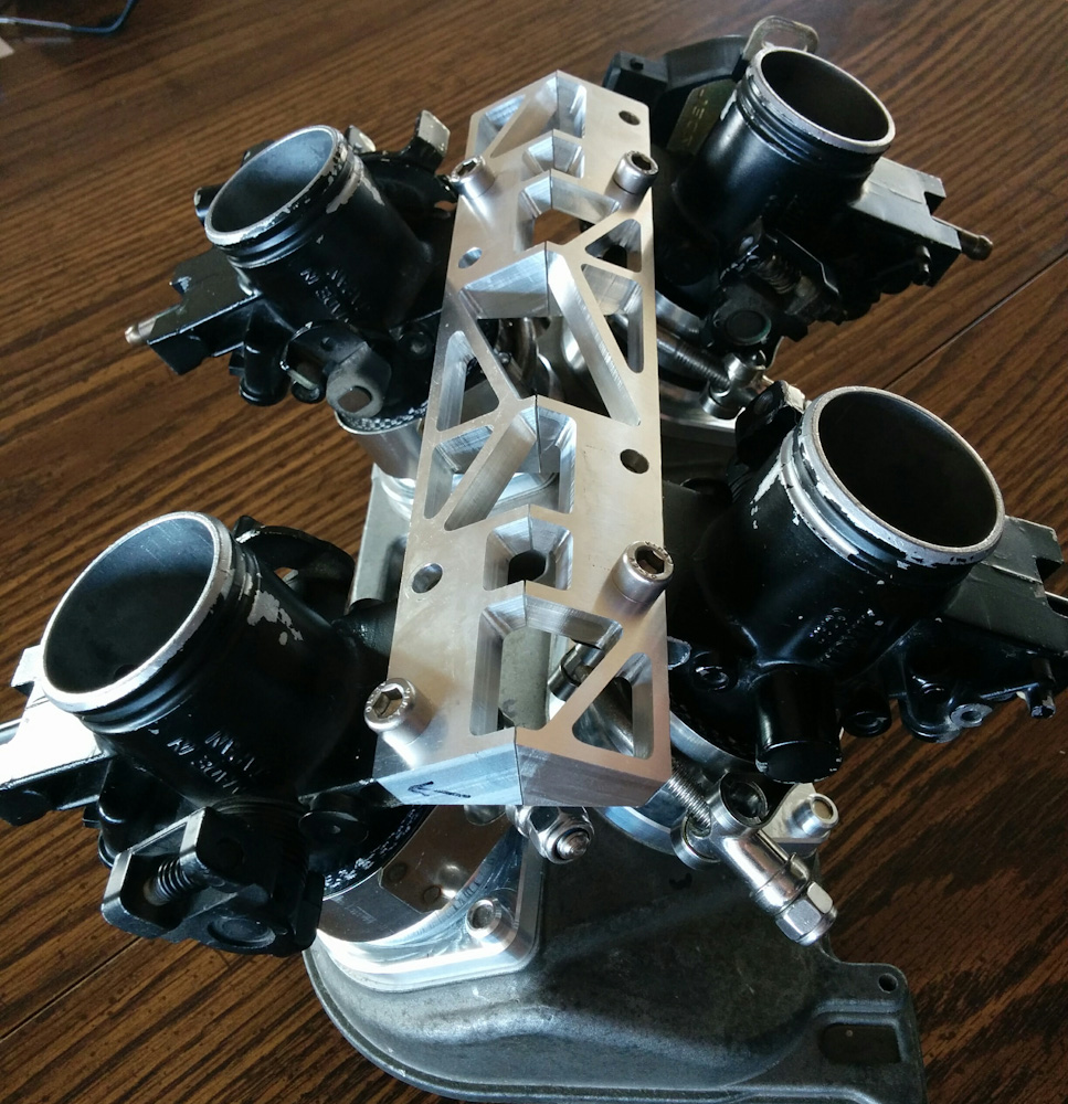
Since the bracket was to be machined on all edges, figuring out how to hold it took some thinking. The first step was to machine the areas where the throttle bodies would mount. This could be done with the part mounted in the vise.
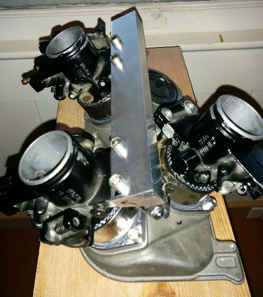
This is a test fit of the bracket to make sure the mounting holes lines up correctly.
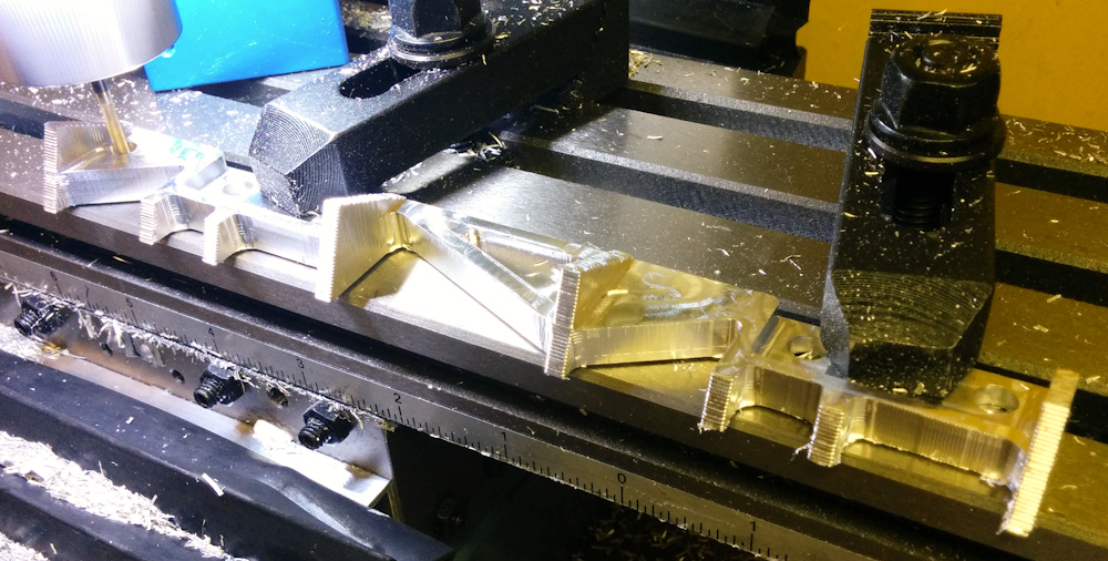
Once the flat areas where the throttle bodies had been machined, I could clamp the piece to the mill table using these areas and machine the rest. To avoid cutting into the table, I placed 0.75mm shims under the piece at the two points where it’s clamped down. I wasn’t sure this would be sturdy enough, but it worked fine.
After machining the two halves, they were test fit again before welding them together. They fit almost perfectly . There is a small gap between the parts, but this is well within the flexibility of the couplings that hold them to the airbox.
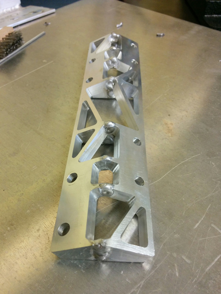
It’s been a while since I did aluminum welding, so I had to practice a bit before I dared to start melting the parts I’d just spent hours making. The welds didn’t exactly turn out spectacular, but I got the parts together with very little warping.
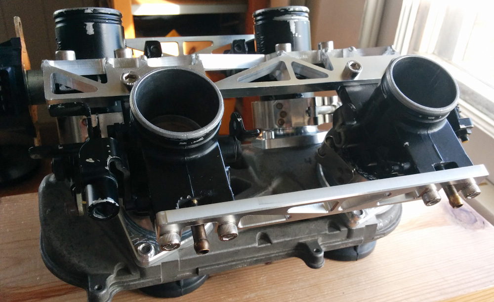
Here’s the final result, the welded-together bracket as well as the smaller ones that attach to the top sides of the throttle bodies. Everything fit beautifully. Compare this picture to the rendering at the beginning of the page. This CAD stuff actually works!
So this was a complete success, the throttle bodies are now held in the correct positions. The next steps are a bit more iffy: The holes where the fuel injectors mount in the throttle bodies aren’t the right depth for the Bosch EV6 injectors I’m going to use. This means I’ll have to actually machine into the throttle bodies themselves, which will be … exciting…
The intake ends also don’t fit into the intake rubbers on the engine, the OD of the throttle bodies, 40mm, is too large compared with the stock carburetors 36mm. I was going to cut down the diameter of the throttle bodies, but there will be uncomfortably little material left if I go that route. It probably makes more sense to try to enlarge the holes in the rubber boots, although I’m not sure how to best do that. But that will be the topic of a later post.
Patrik, I’ve been interested in owning a Honda V4 for quite a while now. I’ve come across a 1992 VFR750F (NC36) that looks like it might be a good buy. This year model, part of the 3rd generation I think, seems like a very good representative of the breed because it has the gear-driven valve train. Unlike the NC30 it has a 180 degree crankshaft. I don’t know enough about the Honda V4s to know which of the two crankshaft configurations I like better, but I do like the sound of the VFR750F on the youtube videos I’ve watched.
Question for you: If I were to purchase this bike I’d probably end up wanting to make it into another fuel injection project. Do you think a ’92 VFR could be made to accept a VFR800 injection throttle body assembly or are there differences between configuration of the two bikes (engine, frame, airbox) that would rule this out?
Hey Greg,
I’m not very familiar with the 750 family, but it appears from Wikipedia that there was a redesign when they went to the RC46 such that the cam gears were moved from between the cylinders (which is like the NC30/RC30) to the side of the engine. This likely means that it won’t fit directly, and it appears from pictures that the throttle bodies for each side are a single piece so it’s probably not trivial to modify them to fit either.
Thanks Patrik,
I’d forgotten about the difference in cylinder spacing brought about by the relocation of the cam drive. Now I’ve looked at pictures of the 750 engine block vs. the 800 engine block and the difference in spacing of the cylinder bores is huge.
This means I’ll go with my already proven method of having an original set of carbs machined to accept injectors (worked great on my GSF400). After that it’s just a question of working out the plumbing. I’ve discovered the VFR750 to be a very tightly packaged motorcycle (not a lot of unused space under those fairings) but I’ve gotten a PDF copy of the Service Manual and it does look like there’s space for the necessary fuel injection system items.
I’m looking forward to this project: the combination of VFR750 styling + gear-driven cams with fuel injection.
Pingback: Microsquirting the NC30, part #22: Mounting the intake rubbers – Patrik's projects