It’s been a while since the last post on the NC30 EFI conversion. I was concentrating on getting the CNC mill up and running so I could make some parts.
As you may recall, I had designed a bunch of little pieces for holding the throttle bodies and attaching them to the airbox that would need to be fabricated. As I’ve gotten more proficient in using Fusion360, I’ve reworked the design a bit, and now with the mill up and running it was finally time to start producing some hardware.
I started with the adapters that would attach the throttle bodies to the airbox. If you look back at the previous post, you’ll get an idea of what we’re talking about. This part is attached to the airbox with two M6 screws, surrounded by guide pins that locate the part precisely.
To get the pins to fit snugly into these holes I did some trial runs to determine exactly how much extra material I would need to remove, which comes down to plus or minus 0.01mm, depending exactly on the diameter of the end mill. At these scales, the backlash in the ballscrews also matter, so the holes aren’t exactly circular. I made a big array of holes with gradually increasing clearance and eventually found a good value.
The next tricky thing was to figure out how to hold the piece. Because of its shape, you can’t hold it in a vise. However, it has those guide pins, so I ended up with a procedure where I cut the bottom surface, including the holes for the guide pins. I then tapped the threads and screwed the half-finished piece into a fixture that I had designed previously. Because the guide pins located the part precisely in relation to this fixture, I could then set the zeropoint for the machine in relation to the fixture and machine the top side.
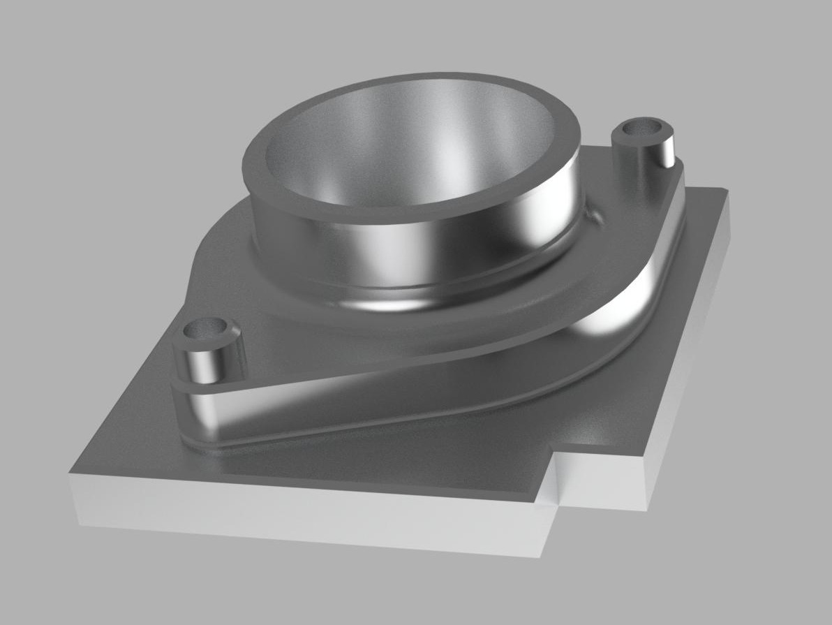
A Fusion360 rendering of the throttle body adapter mounted on the fixture. The cut-out corner on the fixture defines the XY origin.
I made a short movie of one being machined:
Starting from a large block of 6061, there was a lot of material to get rid of, so making these took a while. I also fine-tuned the design after making the first one and trying it out.
One thing I initially neglected to add was a “ridge” on the edge facing the throttle body. The adapter attaches to the trottle body with a short length of silicone hose fastened with a hose clamp, and I realized this is a lot more secure if there are some ridges the hose can bite into. Because of the way the part is milled, this requires undercutting, so I had to get a “slot cutter”, essentially a short, fairly large-diameter endmill with a narrower shaft. To chamfer these edges, I also needed a double-angle chamfer mill which works similarly except it’s angled 45-degrees on top and bottom.
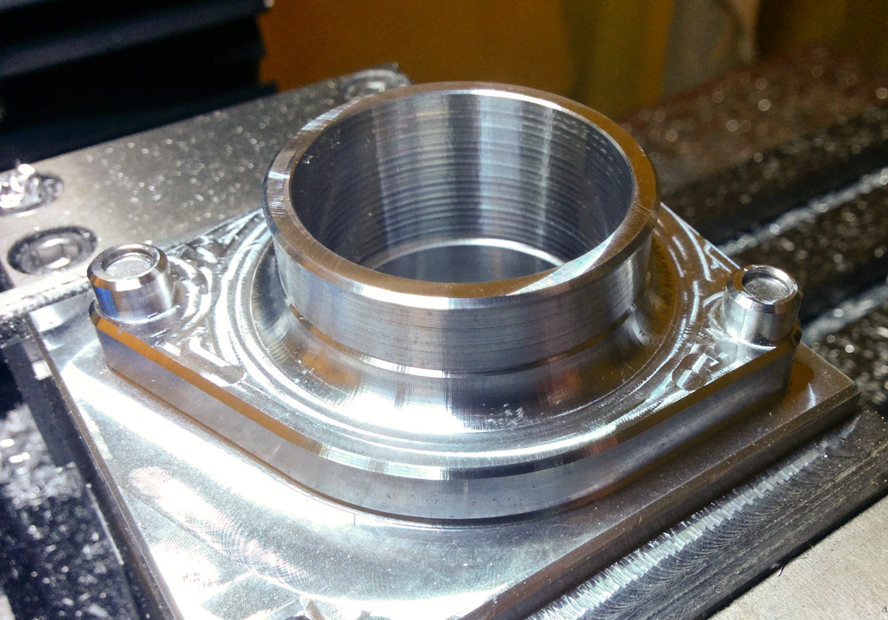
Here’s one of the finished throttle body adapters, still mounted on the fixture. Looks just like the rendering above!
In the end, it worked out great. The silicone hose and the throttle bodies fit perfectly on them. The next part to make was the bracket that holds all the throttle bodies in place together, but that will be the next post.
Very good to see you making progress on the NC30, should be an interesting Spring and Summer.
Pingback: Microsquirting the NC30, part #16: Mounting the throttle bodies – Patrik's projects