Since the last post, the task has been to figure out how to mount all the fuel injection hardware. I decided that this was best done by computer modeling, since there are a bunch of different pieces of hardware that have to fit together correctly, without interference in the cramped space. The “V” engine also makes everything tilted and hard to visualize.
A while ago I got Cubify Design, the “hobbyist” version of a professional-grade CAD program (Geomagic Design). It was the only program I could find that had full parametric modeling capability for a reasonable price ($199). Parametric modeling means you can define your geometry in terms of relations between components, so that you can change the parameters and subsequent operations update automatically. It’s a very powerful way of modeling, which also means there’s quite a learning curve in using the program. I spent quite some time going through tutorials and doing little test projects.
So now it was time for the first “real” modeling task. I modeled up the airbox, the carburetors, and the rubber boots that hold them. This way I could deduce the 3D location of the intakes, which otherwise is hard to determine. I could then “freeze” the airbox and rubber boots in space, replace the carbs with the throttle bodies, and then I would be able to figure out the shape needed for the adapters that would hold them.
This worked quite well, and I actually got to a pretty reasonable result when I ran smack into an unexpected roadblock. I was unable to figure out how to export the model from Cubify in any other file format than “STL”, which is used to describe triangulated solids. This turned my round adapter barrel into a polygon!
After some frustration, I contacted Cubify support, who told me that, indeed, that is the only export option. If you want to export your model in a “real” file format, you obviously is a professional and you should buy the $1999 version instead! They are holding their users data hostage!
About this time, I got a tip from Marco, a fellow Long-Ez builder who, unlike me, is actually making progress on his airplane. (Check out his blog, it’s full of interesting stories related to plane building and workshop stuff in general!) He pointed out that Autodesk is pushing their new CAD program Fusion 360 hard, and it’s free for anyone making less than $100k from using it! Fusion 360 is pretty cool, it’s not just a CAD program, it has an advanced CAM functionality for manufacturing your parts using CNC machines, stress/strain modeling, making ray-traced renderings of your model, and much more. Pretty cool!
The combined CAD/CAM is a killer. Now you can design a fully 3-dimensional part and then generate the CNC program to machine it from within the same program, which is awesome.
So I decided to trash Cubify and start over learning Fusion 360. It’s not as well polished, because it’s a much newer program, and I kept getting hung up on things that were easy in Cubify but had some annoying quirks in Fusion 360. But I persevered!
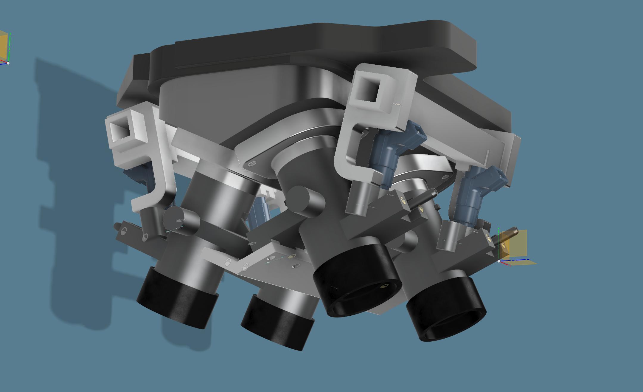
Here’s the throttle body assembly model complete with adapters, injectors, fuel rail, and some of the brackets that will hold the throttle bodies in position. The NC30 wizards out there may recognize that the sub air filter (the protrusion in the top black plastic piece) is on the wrong side. Yes, I managed to model that part mirror-flipped…
This image shows the model right now. The shiny parts are the ones that will be manufactured: the throttle body adapters, the fuel rails, and brackets holding them.
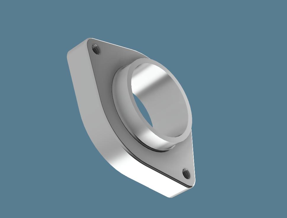
The throttle body adapter. This will be machined out of a piece of Aluminum.
The adapter turned out to be quite simple. As you can see, it’s the same diameter as the throttle body, so I’ll mount them with a short length of silicone hose over the outside.
The fuel rail turned out to be a bit tricky. I had planned to use extruded fuel rail stock from Ross Machine Racing, but it turns out there’s so little space under the airbox that I had to resort to a more custom solution. SDS has a tips page talking about how to build a fuel rail, using 3/4″ square tubing. It’s preferable to use steel or even stainless due to its lower thermal conductivity as it will heat the fuel up less, but given the difficulty of machining I’m going to go with 6061.
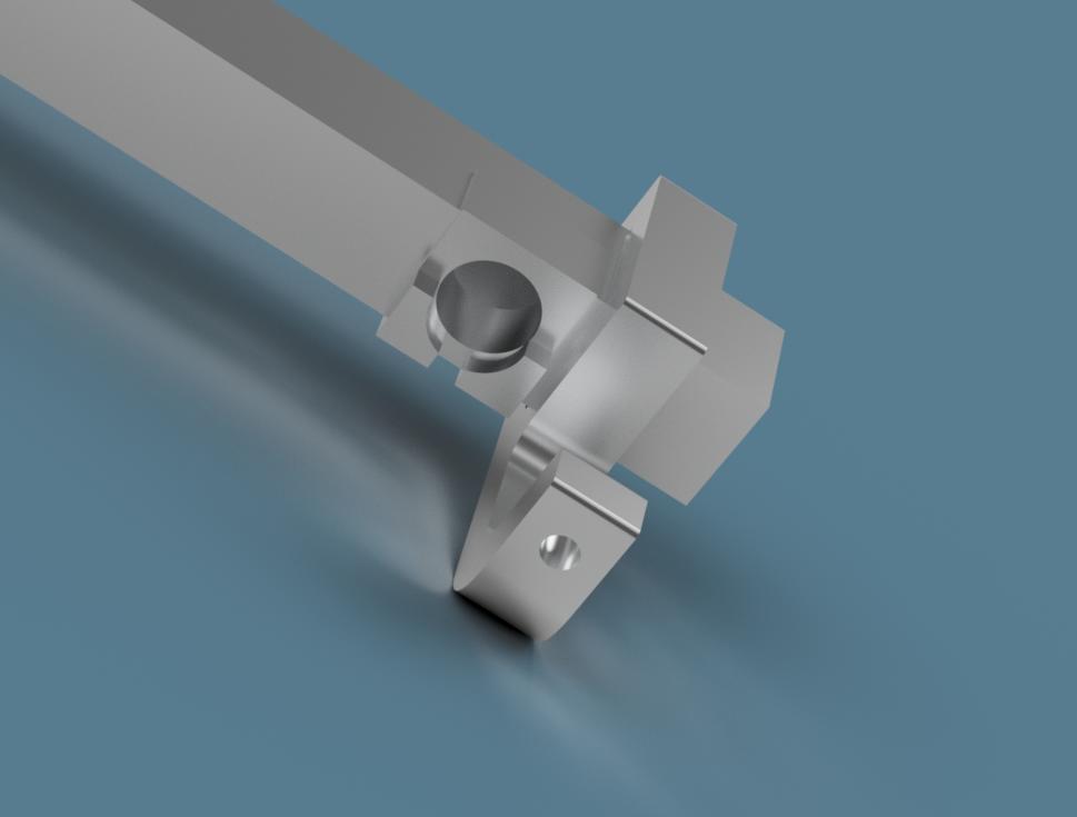
The fuel rail and one of the brackets that hold it to the throttle bodies. The injector will be held by a small square piece of 6061 that has been bored to the proper diameter and mounted in a cutout in the square tube. The small cutout in the bottom part prevents the injector from rotating. (This is an example of Fusion 360’s ray tracing capability.)
In most cases, people use a round “boss” that the top of the injector sticks into, and this is then welded to the fuel rail. The problem with this is that the fuel rail sticks up far above the top of the injectors, and there just isn’t enough room for that. So instead, my injector bosses will be welded into cutouts in the square tube. This cuts down on the cross sectional area somewhat, but there should be plenty of area for the fuel to flow through. I’ll also have to bore out the injector mounting holes in the throttle bodies a bit, I discovered that they aren’t quite deep enough right now. That also gets the injectors about 5mm lower, which helps.
The fuel rails will be held in the correct position with brackets machined out of 1/2″ thick Aluminum. The brackets completely surround the square tube and are held with bolts that screw into the existing holes in the throttle body that were used for that purpose with the stock injectors.
I’ve been a bit nervous ever since I realized how little space there is under the airbox, but I think this model shows that it’s going to work out. However, there’s a bunch of parts that will need to be fabricated. I’m getting set up to do that, too, but more on that later.
I’ve mentioned before that I used the secondary injector array from a Kawasaki ZX636 on my GSF400 (the 636’s airbox-mounted array). It seems that the Kawasaki engineers were working with some of the same considerations/limitations that you are: number one issue being the need to greatly reduce the stack-height of the airbox mounted injector array so it fits neatly beneath the fuel tank (without intruding into and taking up much of the all-important airbox volume).
The injectors used in the 636 secondary array are very short in overall length.
Pingback: A mini mill, with CNC | Patrik's projects
Pingback: Microsquirting the NC30, part #15: Production – Patrik's projects