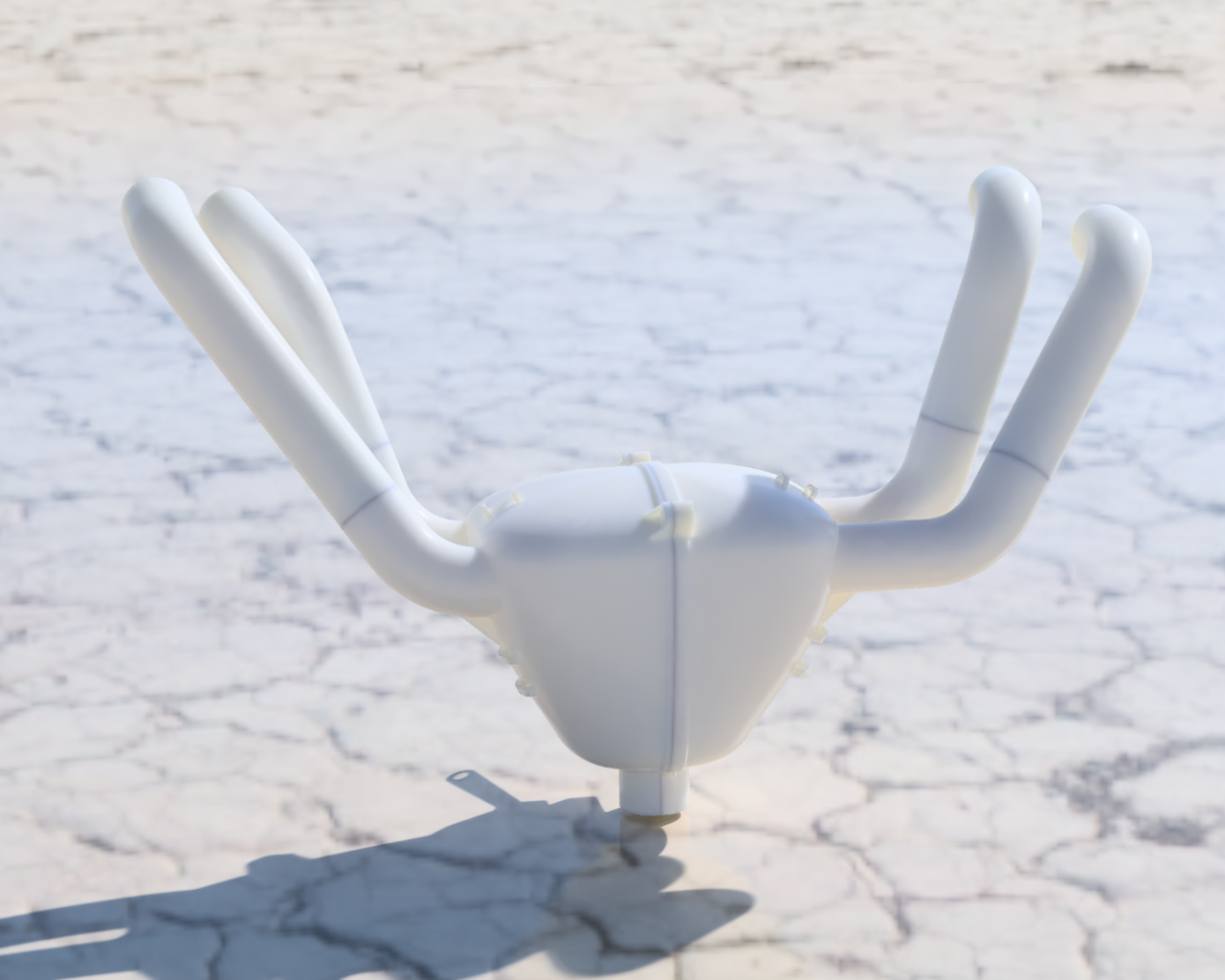
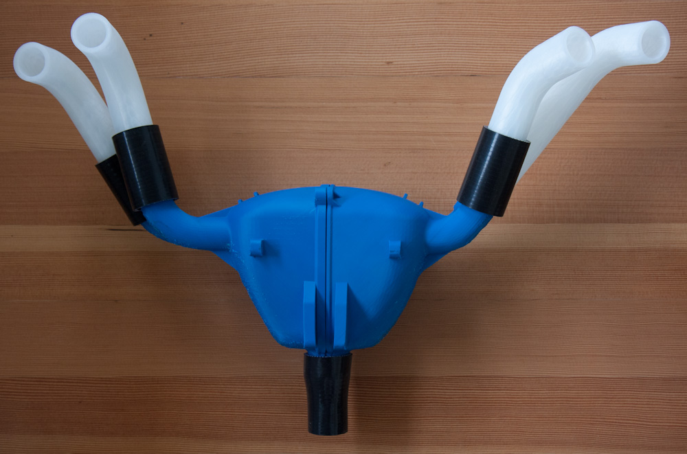
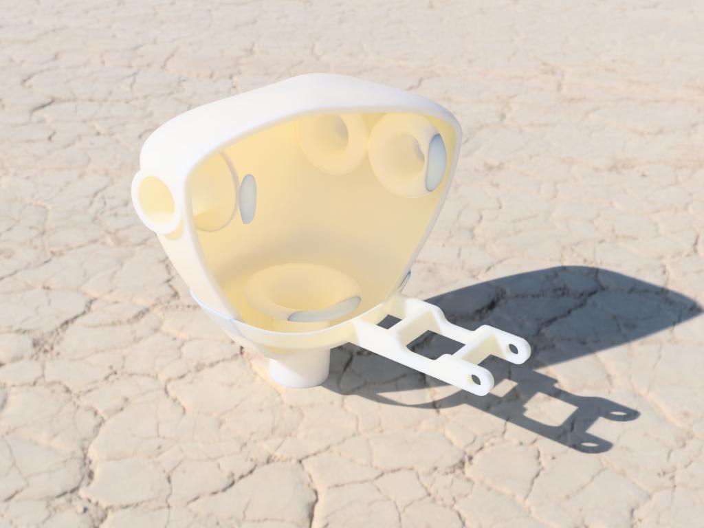
The last post ended with the test print of the plenum. This was a useful exercise as test fitting the plenum in combination with the “Lego” runners indicated some adjustments to the angles of the runners’ exits from the plenum. After fixing that, it was just a matter of printing them…
… or rather, that’s what I thought. I had test printed small pieces with Alloy 910 before and they had come out well. However, each of the plenum halves take more than 24h to print, and a few hours after starting the first half, it became clear that all was not well.
There are many things that can go wrong when 3d printing, especially large pieces. Since each layer is built up by extruding molten plastic on top of the completed part, and plastic shrinks when it cools, the part will tend to “curl” upward. As these stresses build up layer by layer, it’s possible for the part to pop off the printing bed entirely. That did not happen here, but on a smaller scale, printed overhangs, where the freshly printed section is the thinnest, did the same thing. Once it has started, this effect tends to reinforce itself since as the plastic curls up, the extruder will rub against it rather than go above it when depositing new layers. This repeatedly re-melts the top of the part, making it worse and worse.
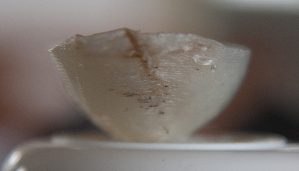
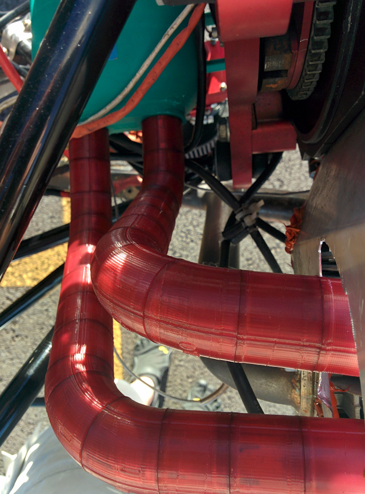
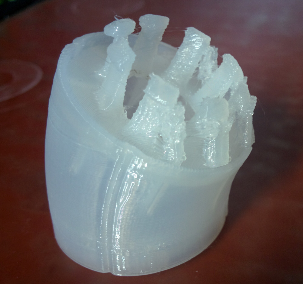
The trickiest problem to solve was the curling up of convex edges. This closeup shows how the layers rise towards the front of the part. it also shows all the cooked plastic crud getting picked up by off the nozzle as the raised edge brushes against it. The brown line is from a nozzle travel move that always went in the same direction and bumped into the progressively more raised edge.
Once started, there are only two ways this process ends: Either the overhang angle of the part becomes more vertical such that the printed edge thickens and eventually becomes stable enough to hold its shape, or it builds up until the printer nozzle can no longer cross over it and the print head jams and loses position. The former results in a bad print, the latter in a complete fail.
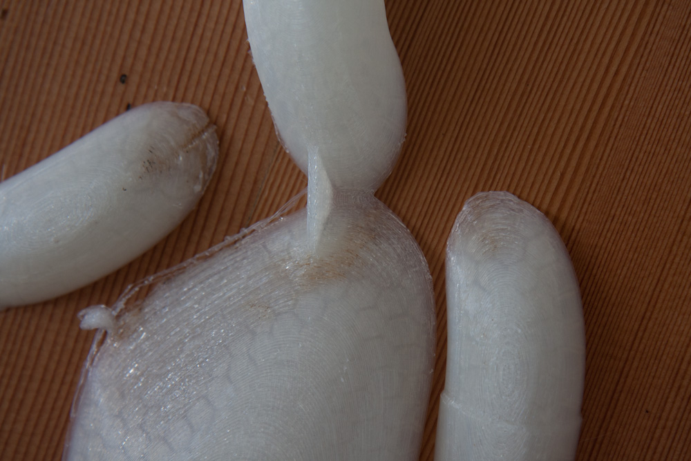
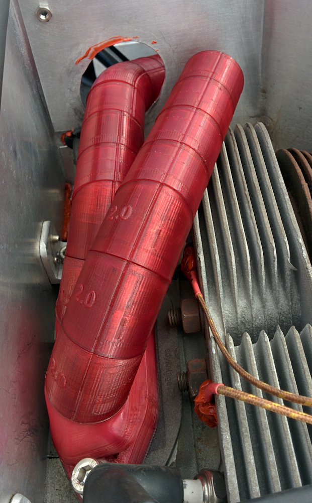
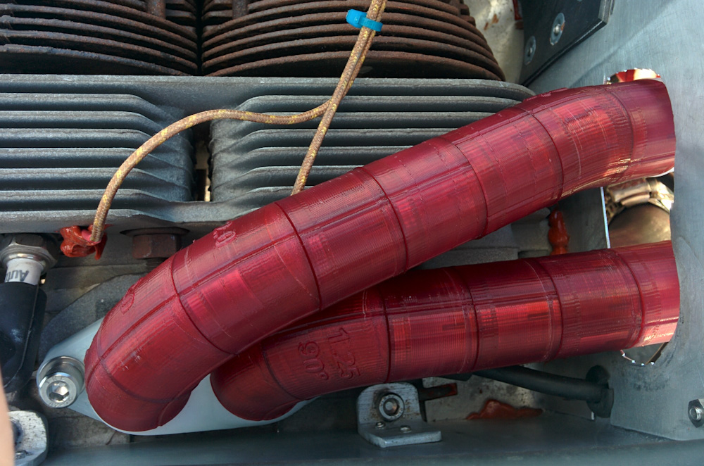
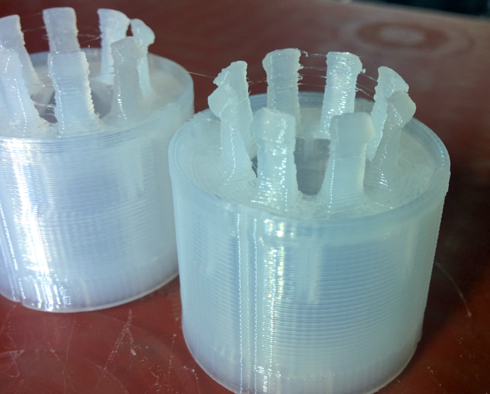
Here’s a print that was aborted due to the upcurled edges. It’s obvious how the structure of the plenum wall towards the bottom is completely disrupted and the honeycomb infill no longer coherent. The part shown in the previous picture is the one on the left.
The edges on my print did not fail, because the edges in question were merged with other pieces of the part before it got that bad, but the result was that the wall thickness was severely reduced and the honeycomb infill destroyed in these areas.
Once the print was done, I proceeded to start prying the supports off and it rapidly became clear that something was seriously wrong. The supports came off easily; too easily, in fact. And as I was prying the supports off, the part itself started coming apart, making crunching sounds as it did so. I could push with my finger on an area and the plastic would make crunching sounds and collapse.
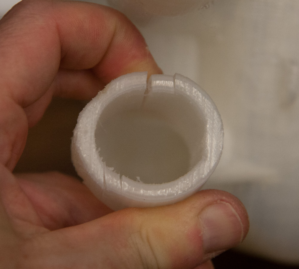
Here’s the initial print. As you can see, it’s cracked along layers just from being squeezed between my fingers. On the correctly printed part, I can barely make the edges move by pushing as hard as I can.
I’m not entirely sure what went wrong here. It’s possible that the 235C printing temperature is too low. The manufacturer recommends 250-260C, and cautions that too low temperature will cause poor layer adhesion. It’s also possible that the plastic did not handle sitting on the heated bed at 85C for 36h. That does not seem likely, because the Alloy 910 material is supposed to be able to handle those temperatures. Also, if sitting on the bed was the problem, the top section that printed last should not be affected, but the entire part is very weak.
This was pretty disappointing. I went back to basics and started testing a wide variety of temperatures, print speeds, fan settings, etc, on a small section of the plenum used as a test piece.
This investigation showed that both when printed at 250C and 260C, the recommended temperatures, the part was extremely strong. I also lowered the bed temperature to 45C, which they also recommend. This did not seem to cause any more warping and in fact made it somewhat better, presumably because the material cooled down faster.
The test pieces also showed that anything printed at 0.2mm layer heights quickly ended up with upcurled edges, while those using 0.3mm did not. Increasing the extruded width from 0.5mm to 0.6mm also helped decrease the upcurl significantly.
However, at 0.3mm layers, the space to the supports (there is at least one layer of empty space between the support and the printed surface) was large enough that some extruded loops of plastic on the bottom layers did not adhere to the rest of the part. Decreasing the layer thickness to 0.25mm seemed to be a good compromise. This still had much less upcurl than when using 0.2mm, but there was also no loose loops on the bottom areas, while the supports still came off cleanly. (Too little space to the support structures and they can fuse completely with the part such that they become practically impossible to remove.)
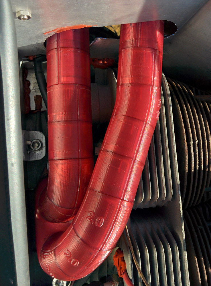
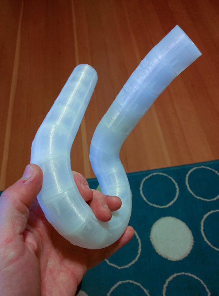
After printing some larger test pieces including a complete runner tube, which requires supports on the insides to hold the “ceiling” as its being printed in, also showed that as long as the bottoms of the supports, which sit on top of the part, had 2 empty layers, they came off cleanly and without too much work, even on the inside of a cylinder.
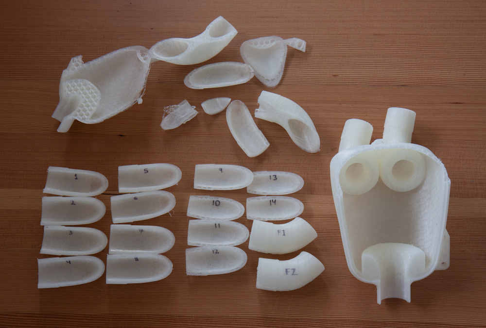
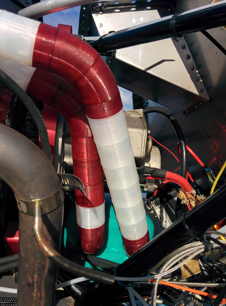
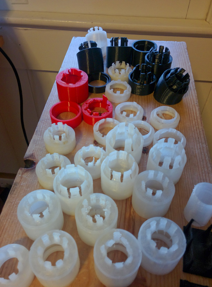
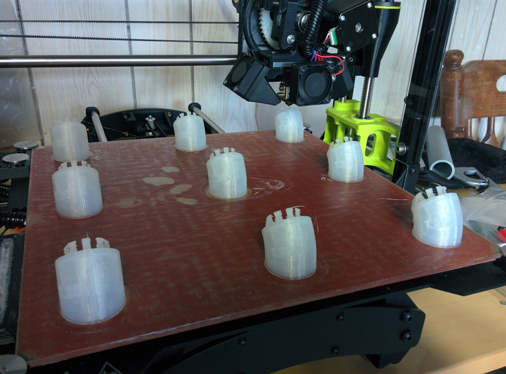
The sum total of all non-production Alloy 910 test prints. The parts numbered 1–14 used a variety of different temperatures, fan speeds, layer heights, and extrusion widths. The larger parts marked “F1” and “F2” tested the final-candidate and really-final settings. The almost-completed plenum on the right is not a test-piece, it ran out of filament with only maybe an hour left…
Armed with this wealth of information, I figured I now had the settings dialed in and printing the part would not be a problem. Not quite.
Even though I had successfully beaten back the upcurl on my small test pieces, it still came back when printing the entire piece. I think this is again a result of the fact that it takes upwards of 5-10 minutes per layer near the bottom when all the supports have to be printed, and the material has even more time to cool than in my test pieces (even though I printed them 4 at a time to make it take longer and more closely mimic the conditions when printing the whole part.)
The final piece of the puzzle was to make sure that all the convex, overhanging edges had some supports to “anchor” them to the base and prevent them from curling. The straight overhanging edges generally were not a problem, so by making a few “lines” of supports going out in the directions where the surface had the strongest curvature I was finally able to print the full 36h print and have it come out basically flawless.
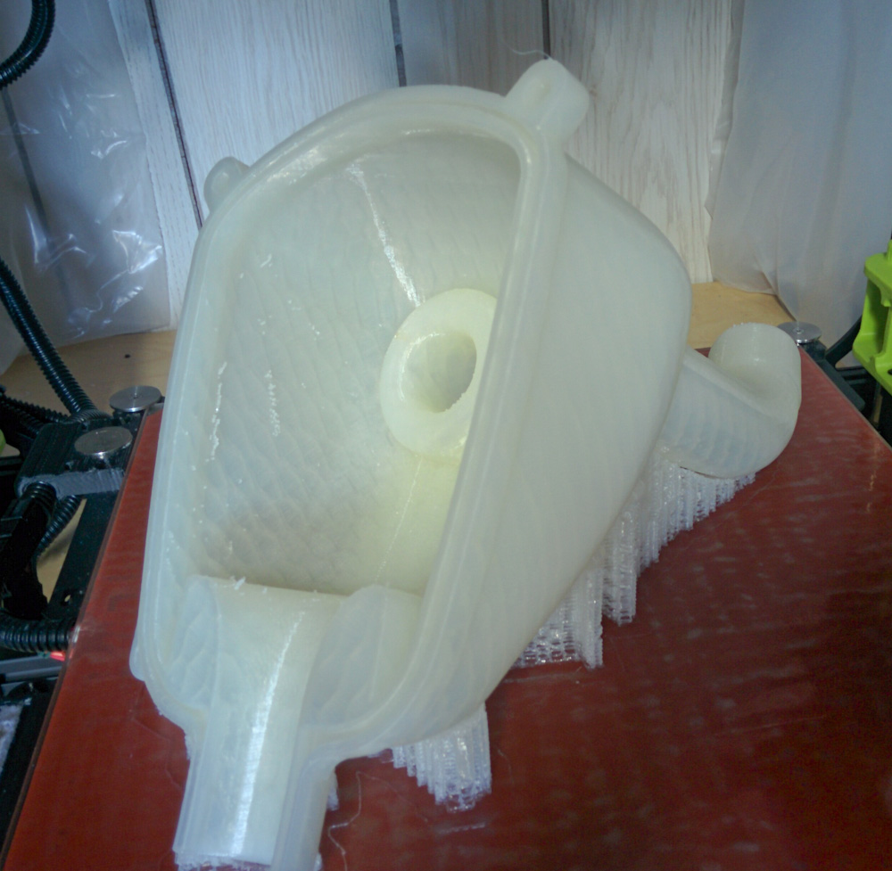
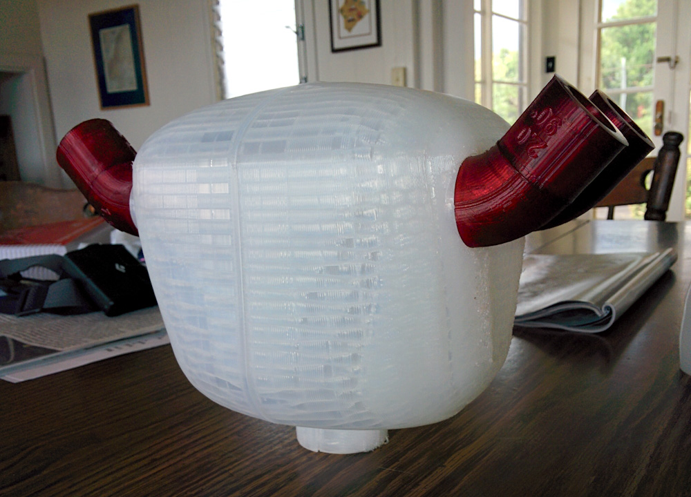
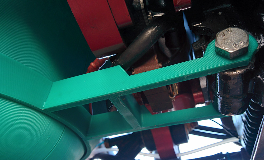
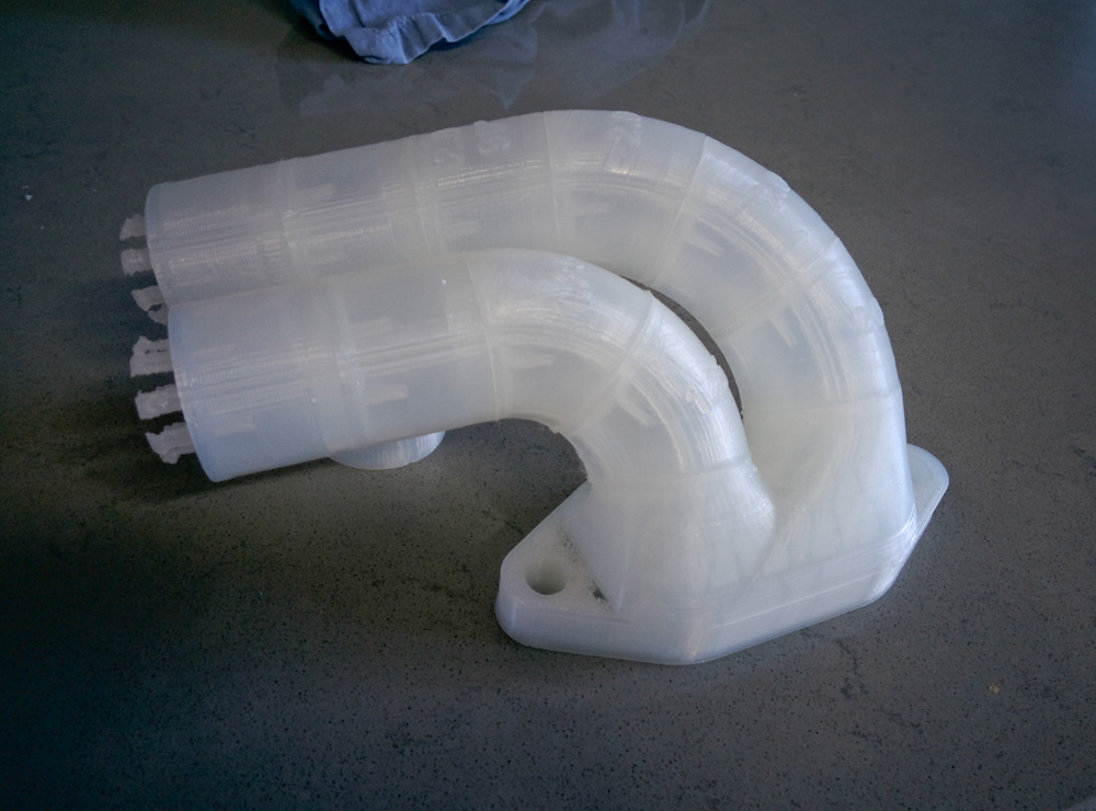
The completed right plenum half, ready to come off the printer. This print took about 36h.
Then it was time to print the other half. You may have read in the previous post how I attempted to make sure the parts were well below 1 pound in weight since that’s how much is on a roll of Alloy 910. Well, I found out that Taulman also sells 1kg rolls, so I ordered two of those. Given that I now had a whole kilogram of plastic, I now let my guard down and didn’t monitor how much was left on the roll…
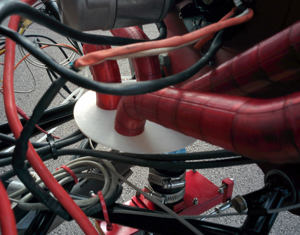
You can see where this is going, right? Yup, it ran out and I didn’t notice. The almost-completed part is to the right in the picture above. It only had probably an hour left of printing on top of the 24h+ it had beeen going… Frustrating, to say the least. At least enough of it was printed that I could use it to double-check that the runners were in the right angles by test-fitting both halves on the engine.
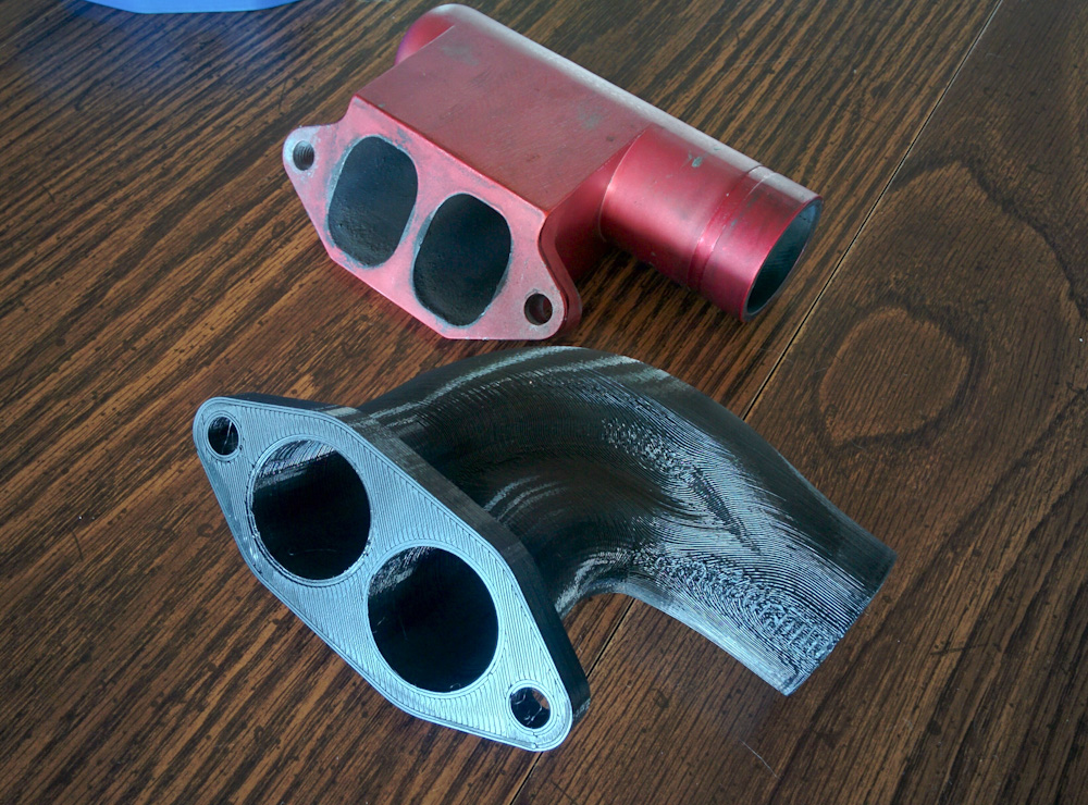
Luckily, I ordered 2 rolls… The left half is once again printing as I’m writing this, and should finish some time early tomorrow. I’m also finishing up the welding of the left aluminum intake flange, so with some luck we might be looking at a test run during the holiday weekend!