The last post outlined the design of the new Aerovee intake, plenum, and the four equal-length runners. Since then, I’ve been busy with fabrication: Two intake elbows had to be CNC’d and welded to the initial runners, the plenum design finalized and its attachments to the runners measured, and then the actual plenum and runners 3D-printed.
So far, most of the work has gone into machining the intake flanges and making sure that the runners get cut to match the plastic test pieces and then welded on in the right position. This wouldn’t be so much of a pain if I didn’t have to drive down to the airport to do a test fit…. which I’ve done four times now, gradually adjusting the runners and breaking off the tack welds. And that’s just the right intake. The left one is just getting finished on the mill.
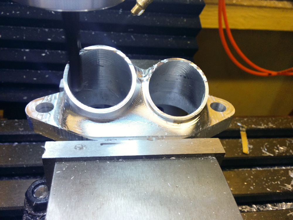
The first intake flange almost done on the mill.
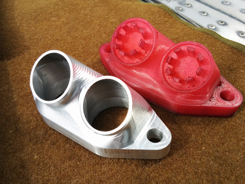
The aluminum flange compared to the plastic fitment piece.
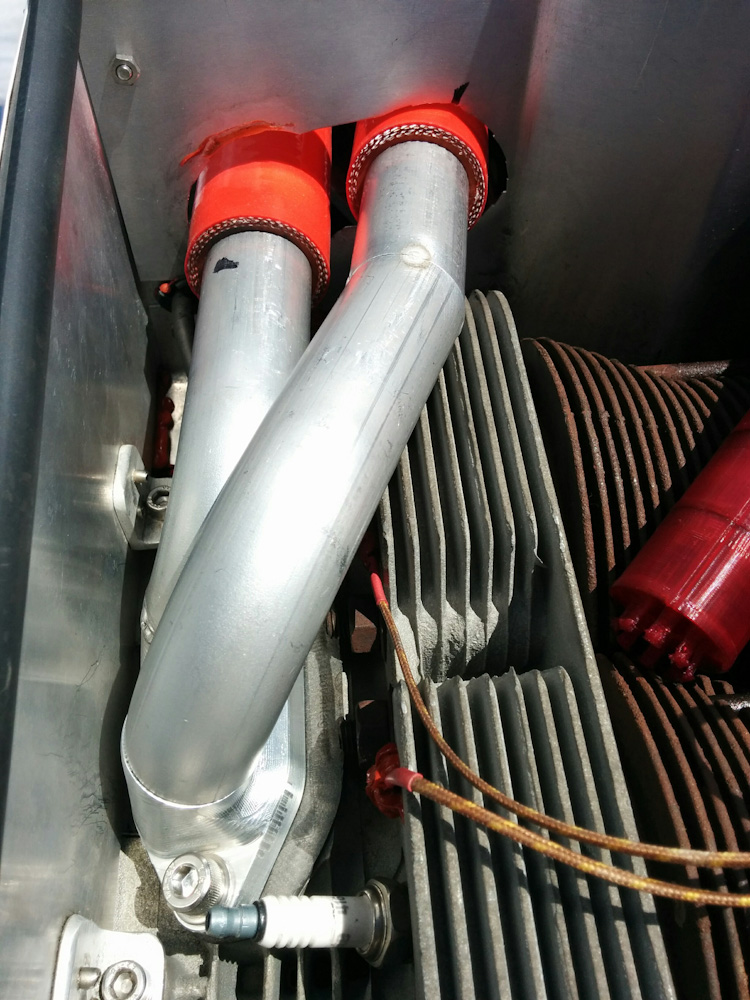
Test fitting the intake runners after tack welding. This has been done a number of times…
While the plenum shape was basically finished in the last post, there were a bunch of little things that needed to be worked out: First, it has to be cut in half to be printable, so it needs a way to get back together securely without leaking. Second, it needs attachment points for the brackets that will hold it to the engine. Third, the initial bend of the runners will be part of the plenum, so those angles needed to be measured as accurately as possible. By making the initial bends part of the plenum, the runners themselves become much simpler to fabricate in that they will each only have a single bend. This saves me from having to clock and weld several bends together when they are finally fabricated in stainless.
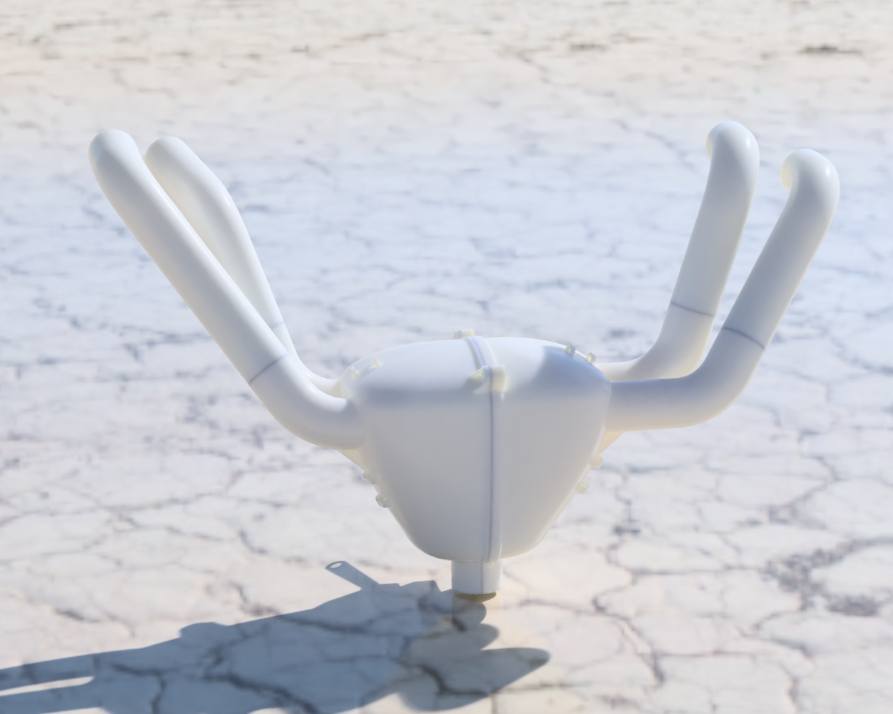
A rendering of the final plenum shape, including the four runners. The runner rotations aren’t necessarily exactly right since those aren’t constrained, but their shapes should be.
Even split in two, the plenum halves including the runners are quite large and complicated pieces and each takes over 24h to print. I also had to tweak the design a bit because the Alloy 910 I’m going to print with only comes in 1lb spools and each piece was going to use up uncomfortably close to a full roll. Since running out of filament at the end would suck big time (not to mention being $40 worth of plastic wasted), I did not want to take any chances there. The current design, as printed, uses about 320g so that seems OK.
To make sure it would print OK, and to be able to do a final fit of the angles of the runners, I printed a test copy using HIPS (which is < 20% the cost of Alloy 910). I also printed the runners in Nylon. I’ll use the printed runners to test run the engine before going through the work of fabricating them in stainless. Nylon should be plenty strong and for a reasonably short run the heat shouldn’t be a problem. (The main issue would probably be radiated heat from the exhaust headers. There is maybe 2″ between the rear exhausts and the intake runners.)
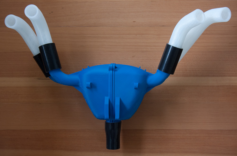
Here’s the HIPS test print of the two plenum halves, with the temporary nylon runners attached. The HIPS print is clearly a bit warped and also did not come off the supports very cleanly. Who cares, it’s just for test fitting.
Remaining work is final fitting, welding the left-side intake flange, and then printing the final plenum. It shouldn’t be long until we can fire it up and see if this was all for nothing now…
Very pretty and elegant work (especially compared to what was there before).
I’d be surprised if there’s no obvious improvement with your redesign of the intake system, but if that’s the case it would probably be an indication of just how poorly the gas flows through the ugly exhaust system (also begging for a redesign?).
Pingback: Printing the plenum: Beating Alloy 910 into submission – Patrik's projects