As explained in the last post, merely making a custom intake elbow for the AeroVee on the Sonex did not yield a satisfactory mixture distribution.
After some discussions, I’ve decided to fabricate an entire intake, using individual runners to the cylinders. This won’t just entail replacing the intake elbow but also designing some sort of intake plenum that the four intake runners can split up into. Ideally you also want these intake runners to have the correct length for the expected full-power RPM around 3100.
The tricky thing whenever making anything like this, either an intake or, more commonly, an exhaust, is to figure out exactly which routing clears all obstructions while bringing the pipes to their endpoints with the correct lengths. A while ago I saw a video on Youtube about someone making a “Lego” for assembling header pipes:
These kits consist of one-inch sections of pipe of the correct diameter and bending radius made in plastic. You can then play around with the routing until you get something that works, and then you know which sections of bends you need to order and how to cut them to get something that fits. Pretty smart!
The only problems are that, first, these guys want like $750 for a kit and, second, since they target the car exhaust market they only have them in diameters that are larger than the 1.25″ intake runners we need.
But now, I have a 3D printer. How hard can it be to design something that can be 3d-printed to snap together like that? Famous last words.
It turns out that getting a good “snap” action that on the one hand holds the sections together securely, while not breaking when assembling or disassembling, isn’t at all trivial. My first design used nGen, a copolyester that’s easy to print and is pretty cheap. However, it turns out to be far too brittle to work for this application.
My next try was to use the PC-max polycarbonate that I printed the intake elbow from. This is much stronger and less brittle than nGen, but my designs still snapped almost right away. I attempted to use the “static simulation” in Fusion 360, where you can take your part and see how it will react to applied forces, to get something that could deflect the required amount without cracking, but that didn’t really work out well either.
Looking for something that was more elastic, I tried a roll of Taulman Alloy 910 that I had bought a while ago but never used for anything. This is a nylon blend, so is more elastic, but it still cracked. Nylon seemed promising, though, and looking at Taulman’s page about “which filament to choose“, it seemed that their “Bridge” Nylon would be a good alternative. It doesn’t have as high tensile strength as either 910 or PC-max, but more importantly it can deflect a lot more before breaking. (It’s also cheaper than any of the other alternatives which is good since this project would require manufacturing a large number of these sections.)
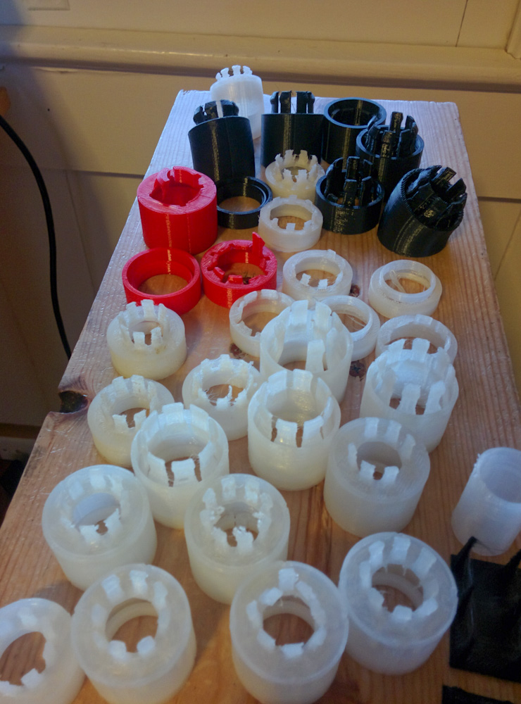
The collection of failed attempts. The ones in red are the nGen, black is polycarbonate, and the white are the Taulman 910 and Bridge nylon.
My first experiments with Bridge did not go super well either. The trick is to get the “tabs” that will snap in and hold the section to be long enough that they don’t break when deflected the required amount, while still being strong enough to hold the piece securely.
In addition, nylon is tricky to print because it is very hygroscopic and absorbs water like crazy. If the filament is not totally dry when you then try to print with it, the nozzle sizzles like a frying pan and little pops of steam shoot out. Needless to say, this wreaks havoc with print quality. Surprisingly enough, even the rolls directly from the manufacturer, vacuum packed with desiccants, are not sufficiently dry when opened.
Once I realized that even if you don’t hear any sizzling, the filament can still have enough moisture to ruin the print, I put the roll in the oven at 75C for five hours and it was like night and day. I also made (printed!) a box with desiccant the filament can be stored in while reeling it out for printing, because with the humidity here the print quality is ruined again after the filament has been sitting out for just a few hours.
The other trick was to get the print settings dialed in. While not very critical if you’re printing some larger or more solid part, these thin tabs would either get big blobs stuck on them from extra plastic oozing out of the nozzle or, if you tried to dial it back too much, be too weak and snap from missing plastic. To figure out the best settings, I set up a couple of grids, systematically varying parameters.
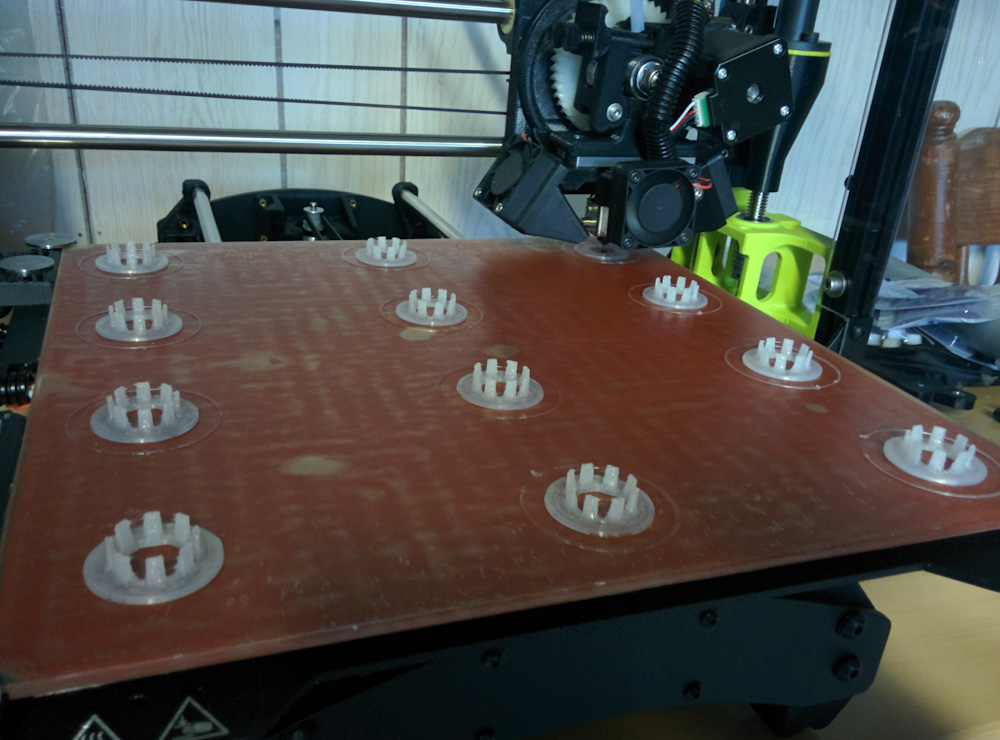
Here’s one of the test grids, printing just the tabs with a bunch of different settings to see which ones worked best.
Finally I came up with something that seemed to work.
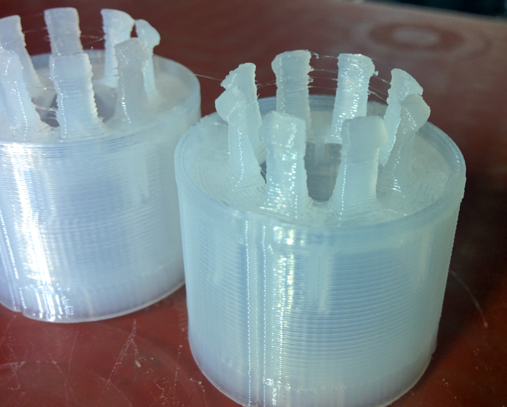
Here are two straight 1″-pieces printed with some settings that work well. Cosmetically, there are still artifacts and some stringing on the tabs, but they work reliably.
It was then a matter of designing all the different pieces needed and switching to mass-production mode. The intake is 1.25″ diameter, and it appears those are available with bend radii of either 2″ or 1.25″, in some combination of 15, 90, or 180 degrees. It all comes out to 7 different types of sections.
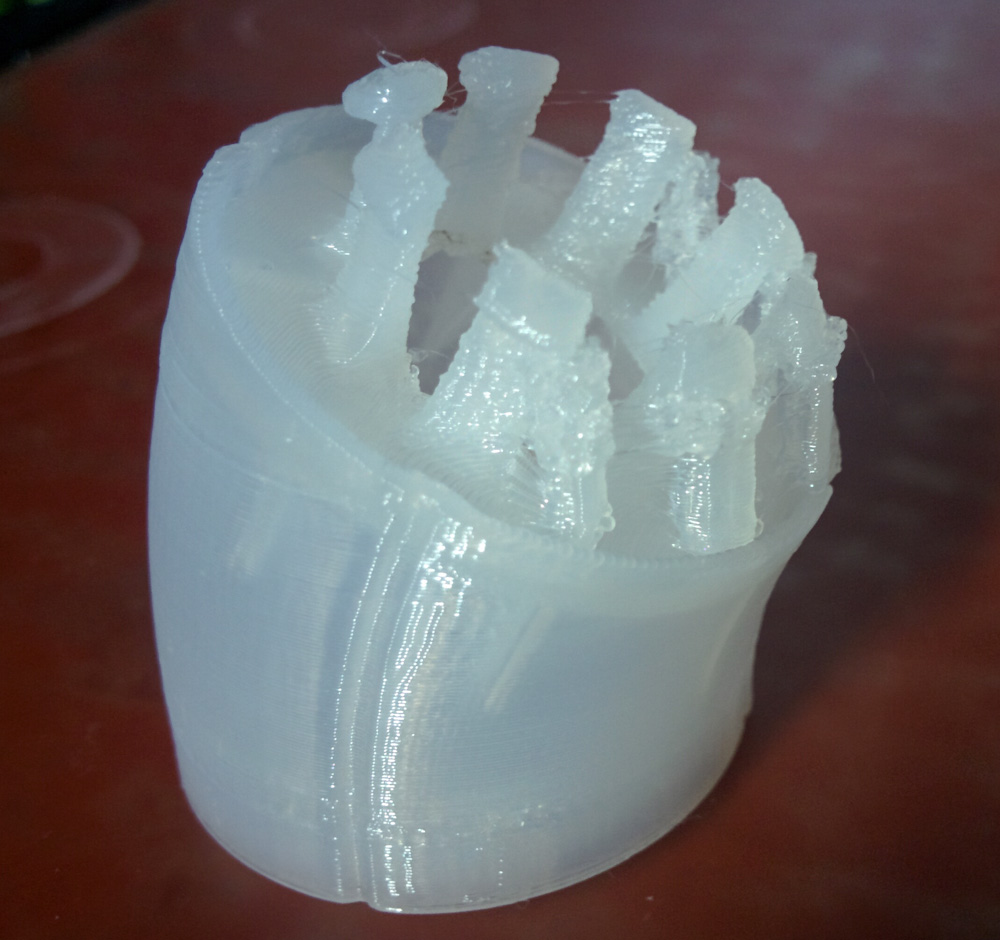
This is a 1″-long section of a bend with 2″ center line radius. Since the top ends up slanted, you have to use supports when printing the tabs (and also some on the inside of the pipe.) The lines along the perimeter is so that you can line up several bends in the same plane. There is also a tab on the inside of the female end that holds the parts in any of 8 different rotational angles, making it easier to line up a series of bends in one plane, or 90 degrees off, etc.
Each piece takes somewhere between 40 minutes for the straight sections to 2h for some of the bends (you have to use a finer layer separation over a larger height for the bends since the tabs are all at different height and you want to resolve their shape well.) To make printing more of them reasonably efficient I’ve set up a script that prints 9 at a time. With a 3×3 grid, the TAZ6 print head has enough clearance that it can print one whole part before moving on to the next one without bumping into it. This is preferable to printing them in parallel since moving between them for every layer takes much longer and also results in a lot of strings being pulled between the part. It’s much more efficient to just do one part at a time.
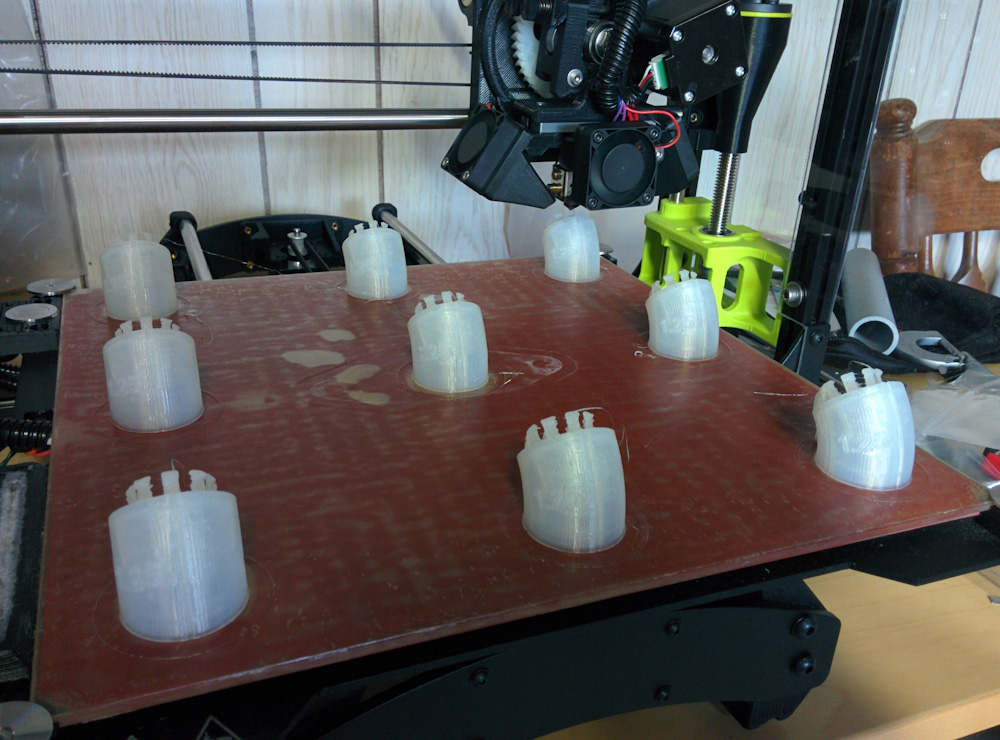
A grid of 9 bends being done in one batch. This takes about 18 hours to finish.
At this point I have enough parts that I think it’s time to go down to the airport, pull the cowling, and try it out. They hook together well and hold their shape at least until you get something tens of inches in length.
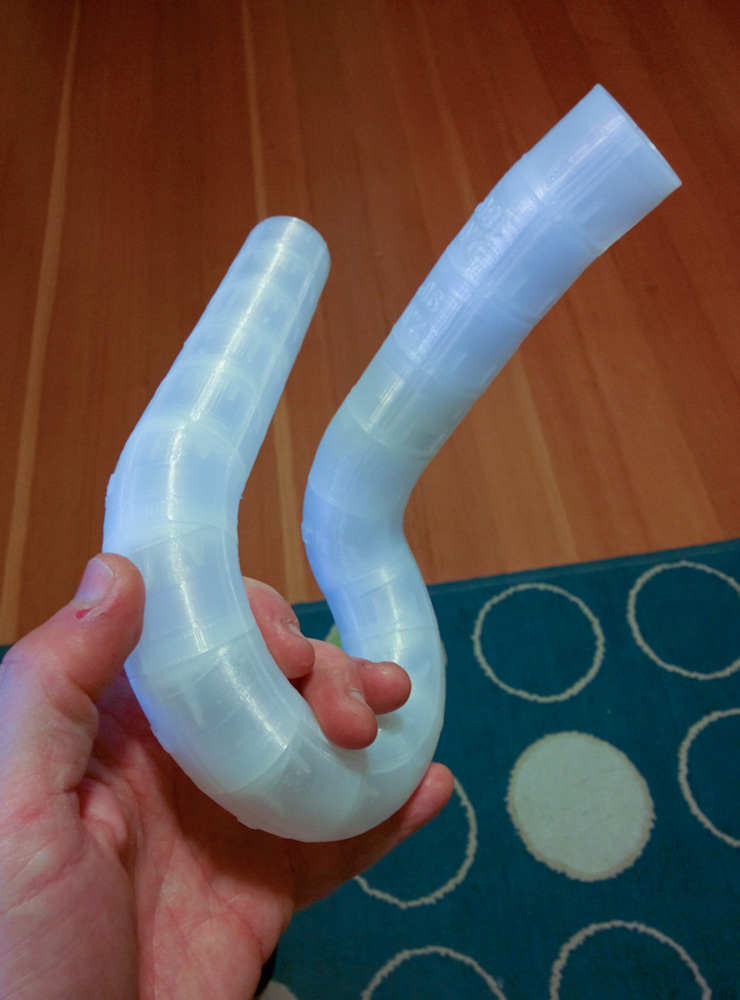
A demonstration of how this is going to look. By using a number of pieces with the same radius aligned in the same plane, you know you have a shape that you can cut from a single 90- or 180-degree mandrel bend.
I also had to have a way to hold the start of the intake at the right place, so I designed an intake flange with attachments for where the two runners will go. This uses the same measurements that I already had from the intake elbow. This part can be bolted to the engine to provide a starting point.
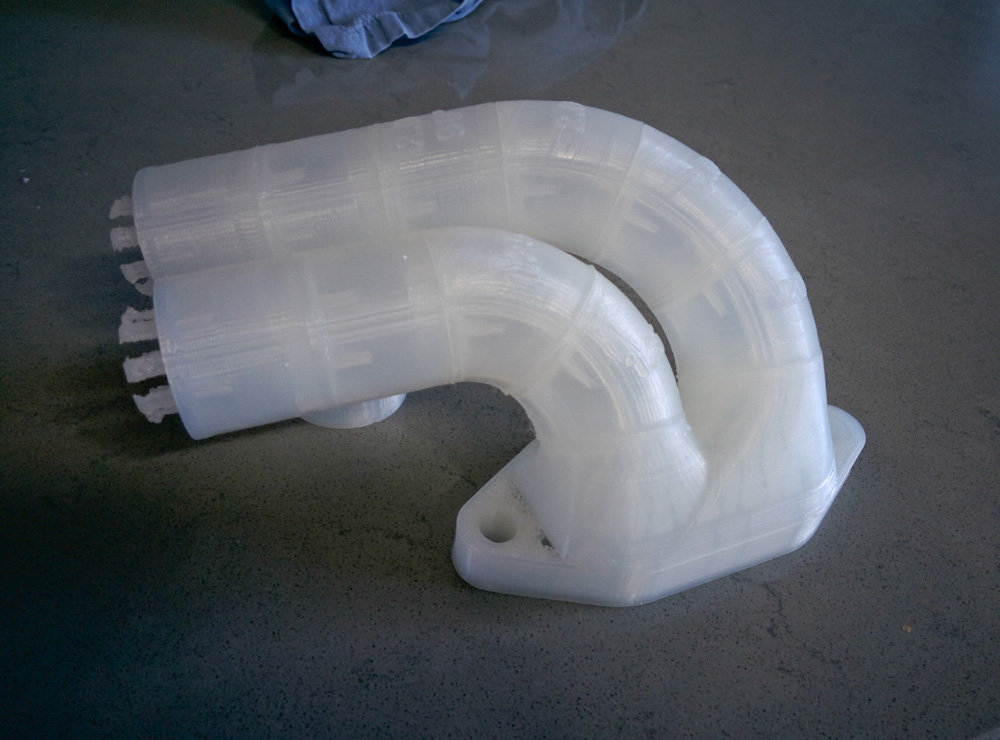
For the mounting on the intake, I designed a flange with two attachment points in what I hope is the right angle to exit the engine. I’m pretty sure that’s going to work since I know the angles the custom intake elbow used, and with a 1.25″ bend on the left (rear) runner and a 2″ bend on the right (front) one, they should clear the cooling fins on the head and be able to both exit rearward. (Once the routing is worked out, this part will be made by CNCing the flange and welding two aluminum mandrel bends on it.)
So, that’s where this part of the experiment is now. I’ll try to get down to the plane next weekend and figure out how to route the runners. Once I know the angles they will come down with, I can design the attachment points on the intake plenum to match, figure out which mandrel bends I need to buy, and get to work actually fabricating it. It’s going to be a semi-long process, for sure, but I’m convinced this will fix the mixture problems once and for all (and hopefully also give more power, if the intake is tuned correctly). Stay tuned!
Pingback: Intake design: Plenum and runners – Patrik's projects