In the last post, I showed my DIY pipe “LEGO” kit that I would use for modeling the runners. Once I had those all fabricated, it was time to go try it on the airplane. To get an idea for how a plenum would fit, I just made a flat disk with four attachment points on it.
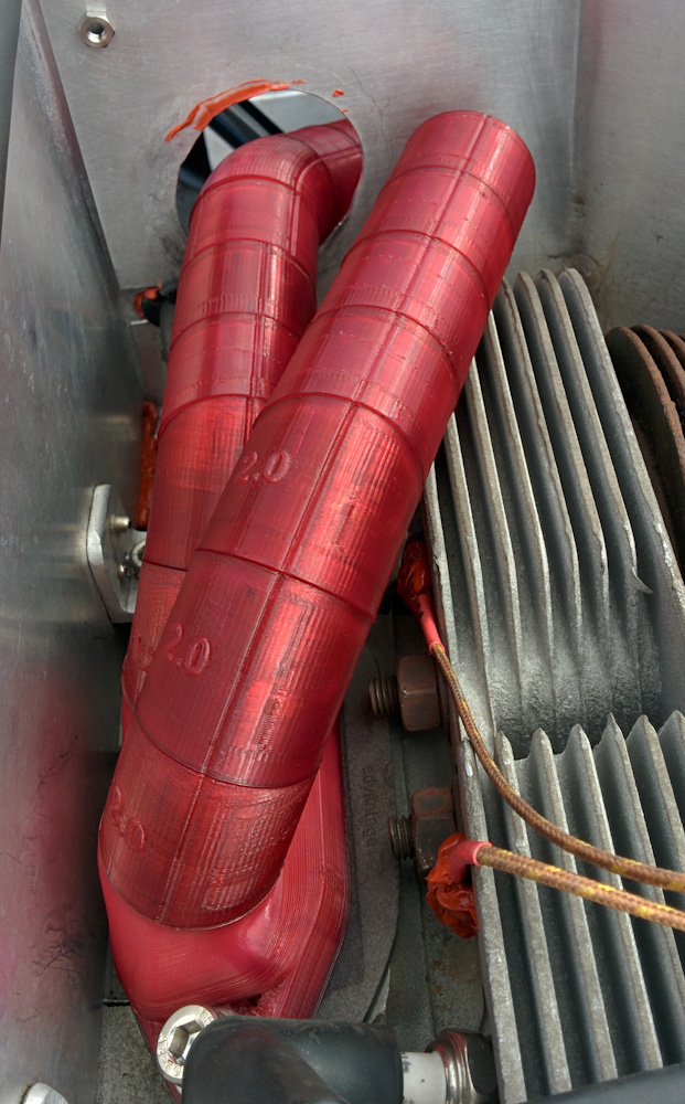
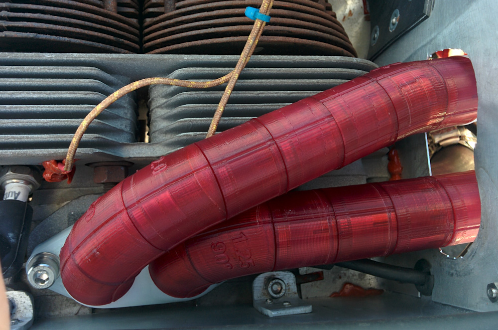
Here’s the first indication of how the intake flange with the two bends will look. (Note the snazzy red-dyed nylon. Nylon takes dyes very well, so I had to try it. And, yes, I’ll have to cut a hole in the rear baffle.)
My first idea for a plenum was to put the four exits on the top. However, I had not counted on the starter, at the top of the picture. To get the runners going to the left cylinders to clear the starter, the plenum would have to sit very low. This does not leave much room to fit a plenum, since the carburetor is sitting as low as it possibly can go right now. I also started out with a cylindrical cross section, but the space in the front-back direction is quite constrained due to the engine mount plate and the engine mount.
The first try did not work at all, but yielded several important design considerations:
- The starter constrains everything to not go higher than about the crankshaft axis.
- If the runners exit the top, there is not enough space to fit the required plenum volume and still fit the carburetor.
- In addition, the low plenum makes the runners too long.
The last point warrants a little explanation. It looks like an intake runner tuned for 3100 RPM with the AeroVee crankshaft duration should have a total length of 21-23″. That includes 2.25″ from the valve to the flange inside the cylinder head, about 1″ for the curved flange, and about 1″ to end the runner inside the plenum, leaving 17-19″ for the runners themselves.
The solution was obviously to make the plenum larger so the runners attach closer to the cylinders. This was accomplished first by changing the design so they would exit on the sides rather than the top and, second, by making the plenum wider at the top, moving the attachment points outward. This resulted in iteration number 2.
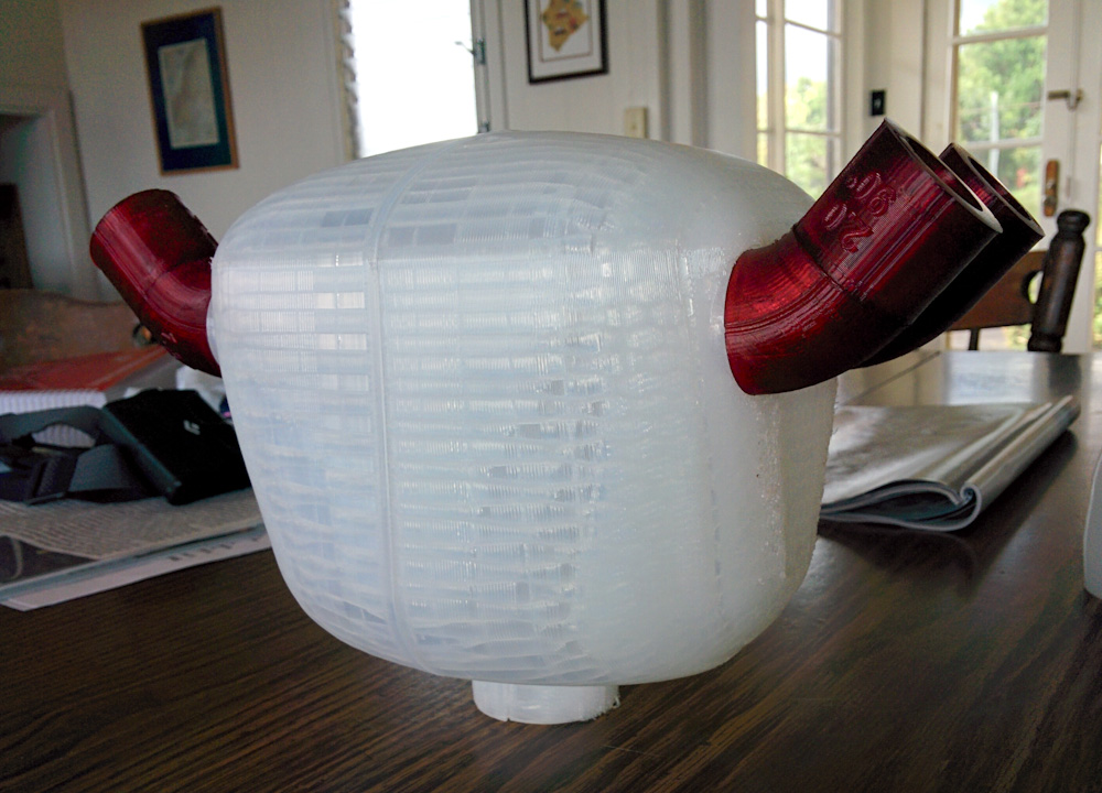
This is the second iteration of the plenum, with side outlets.
This one was better, but it could be made wider at the top and be taller, since there now was a lot of space between the inlet on the bottom and the carburetor.
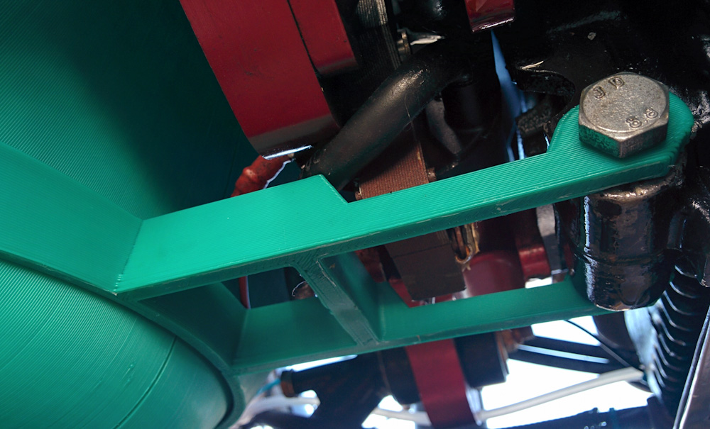
For the third iteration, I also made a bracket to attach the plenum to the lower crankcase bolt. This is where the original intake pipe attaches, so it provides a good reference point to keep the plenum in a fixed position to match the runners against.
For the third iteration, I switched from printing the test in Nylon to HIPS (High-Impact PolyStyrene.) Printing these plenums use a fair amount of plastic and HIPS is much cheaper. It’s also much more brittle and not flexible at all, but that really doesn’t matter for the plenum since it doesn’t have any parts that need to flex.
To be able to locate the plenum reliably, I added a bracket that attaches to the crankcase bolt in essentially the same way the original intake does. (The plenum moves with the engine, so it can’t be attached to the engine mount since the engine is mounted in flexible rubber mounts and moves around.)
The third iteration was a further improvement, but it could be made even wider without the outlets while needing to be slimmed down a bit at the bottom to clear the engine mount.
Finally, the fourth iteration seems like it will work. It clears all other parts, the inlet is located at the right height for the carburetor to attach to it, and I managed to route all four runners with a length of 19.5″ from the flange to the plenum.
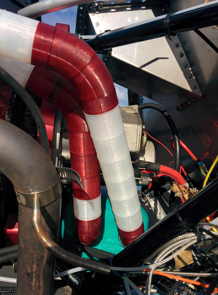
The runners going from cylinders 1 and 3 out through the baffle (yes, I cut it. It can be fixed if this experiment doesn’t pan out.)
The runners from cylinders 1 and 3 going down to the plenum.
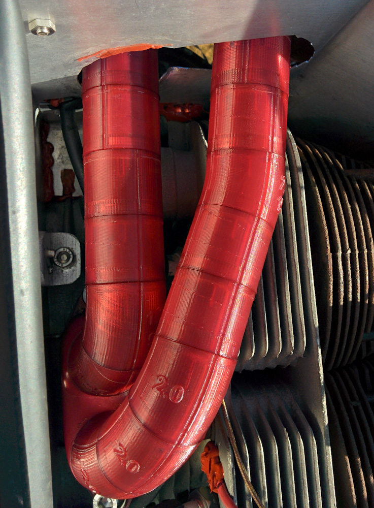
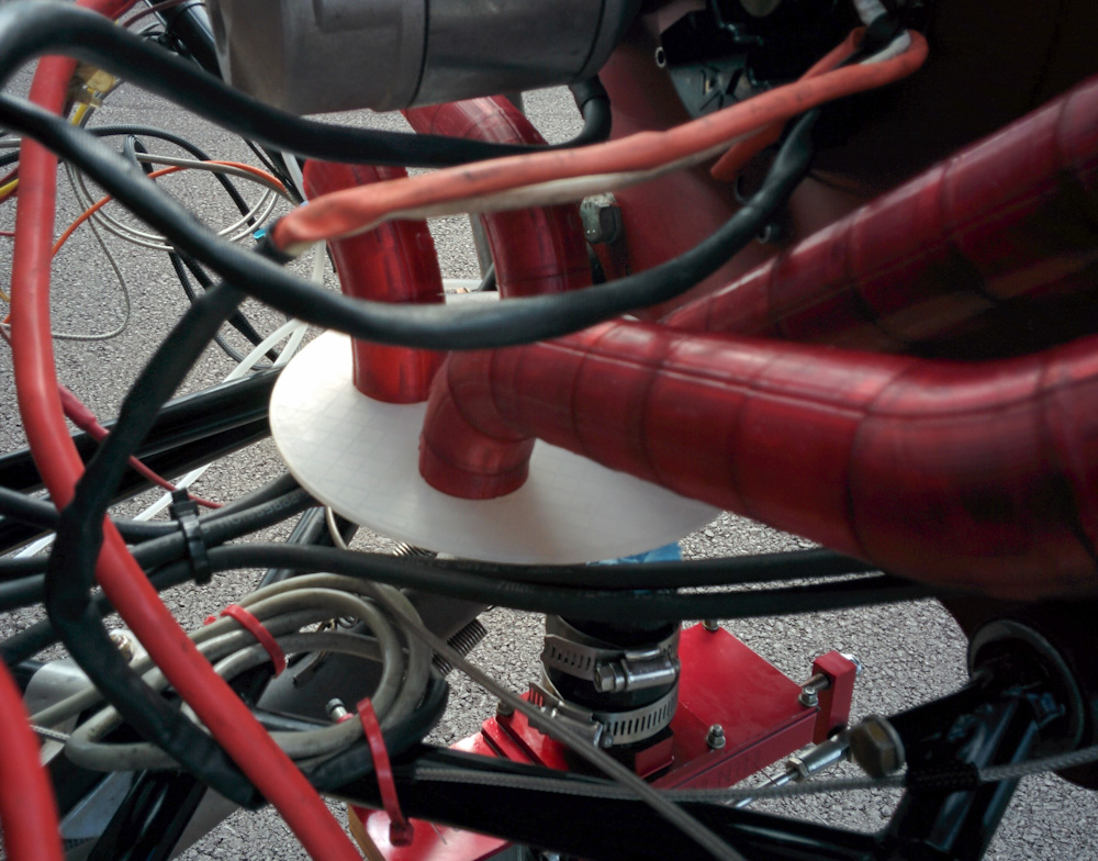
The runners for cylinders 2 and 4, on the right side. This part is practically symmetric between the two sides.
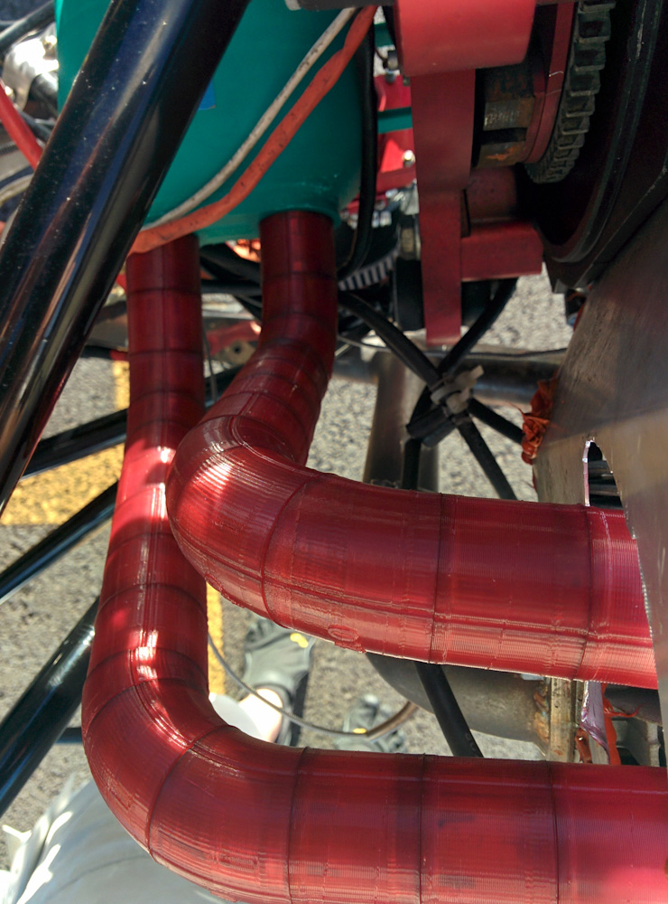
The runners for cylinders 2 and 4 going down to the plenum. Note how these take a noticeably more perpendicular route compared to the 1/3 ones which cut the corner. This is because cylinders 2 & 4, on the right, are located a few inches further rearward than the ones on the left, so to keep all the runners the same length they need to curve around a bit more.
It’s probably hard to see in the pictures, but all four of these runs make up 19.5″ in length. The runs will probably require a little bit of adjustment, because when you clip 19 of those plastic pieces together there’s a fair amount of play, but that should be fine.
The plenum itself will have internal trumpets for the outlets. I made a cutaway render in Fusion of how it will look:
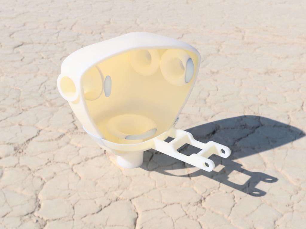
Cutaway rendering of the plenum from Fusion 360. The trumpets are necessary to minimize disruption to the airflow as it enters and exits the plenum.
The intake sections that attach to the cylinder heads will be made of 6061. I’ve already started milling one of the flanges, to which the pipes will attach, on the CNC mill. Then pipes will be welded to the flange to make the two 90-degree exits. I anticipate the aluminum sections to go out through the rear baffles, until the curves start. From there on, I think they’ll be made of 304 stainless, but first I’m going to test run the engine with printed, plastic, tubes to make sure it runs OK.
The plenum itself will be 3D-printed out of Taulman’s Alloy 910 Nylon. It’s a Nylon blend that has one of the highest tensile strengths of all 3D-printed materials, along with the great durability and chemical resistance of Nylon (the plenum will have fuel going through it, remember). Using the static stress simulation in Fusion 360, I’ve determined that it should have sufficient structural strength for the stress the engine-induced vacuum at idle will pose.
In the end, we’ll see if it works. It’s an Experimental, remember!
Is there a more horrifying sight in the car/motorcycle world than a spark plug with the word “Autolite” printed on it? (Surely there’s a manufacturer-recommended plug for that engine).
Hahaha, you have some sharp eyes there.
Straight from the AeroVee installation manual:
“Spark plugs ….. Autolite 4163 or equal”
I don’t know anything about spark plug brands, all my bikes use NGK and that’s where my knowledge ends. What do you have against Autolite?
Yeah but… the same guy who wrote the “AeroVee installation manual” also designed the intake and exhaust systems.
Hmm. Good point.
https://vwparts.aircooled.net/VW-Spark-Plugs-s/65.htm
Pingback: Intake Fabrication – Patrik's projects