The AeroVee Volkswagen conversion engine used for Sonex aircraft is notorious for having poor mixture distribution between the cylinders. During my test runs, I’d noticed that the #4 cylinder (ordered in conventional crankshaft order starting with #1 nearest the prop, which makes #4 the right rear cylinder. For some reason Sonex uses a different numbering scheme) was always the one whose cylinder head temperature overheated way before the others. The rear cylinders normally will run hotter since they naturally get less cooling airflow than the front ones but, as the following will show, they also run much leaner than the front ones.
In reading other people’s experiences, this appears to be fairly universal for all AeroVee-equipped Sonexes. Looking at the intake design, it’s not hard to see how there may be a mixture imbalance. Unlike most intakes that have an intake plenum from which individual runners go to the cylinders, the AeroVee looks very different. The AeroCarb is attached directly to an intake pipe, which splits into left and right branches. These branches go all the way up to the cylinders (about 20″) before ending at an “elbow” mounted to the cylinder head. This elbow has the runners to the two individual cylinders going out at right angle from the incoming pipe, which then dead-ends.
There are several features that seem questionable about this design. First, the two cylinders on the same side of the engine fire consecutively, 180 crank degrees apart. This means that the intake events for the two cylinders that are hooked up to the same intake are not evenly spaced in time. There is 180 crank degrees between the front intake stroke to the rear one, and then 540 degrees before the next front intake stroke. For this reason, exhaust pipes usually merge two cylinders on opposite sides (a “crossover” exhaust), which makes the pulses evenly spaced in time.
The same principle applies to the intake. Since the two intake pulses that share the same intake runner aren’t evenly spaced in time, they won’t affect each other the same way. This gives rise to a fundamental asymmetry.
The other questionable design feature is the intake “elbow”, which just splits the individual cylinders off at right angles. The fuel droplets in the intake charge have higher inertia than the air itself, so when the air makes the 90-degree turn into the “first” cylinder, i.e. the rear one, the fuel droplets will naturally have a tendency to miss this turn and continue to the front cylinder. (In fact, this is exactly the principle by which a device called an inertial separator, which is used to separate particulates out of gas, works.) With this effect in mind, it does not seem surprising that the front cylinder would be running much richer than the rear one; even if the average mixture is correct, more of the fuel will go to the front cylinder than the rear one.
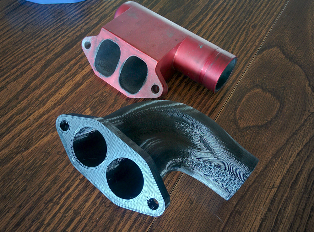
This photo shows the red stock intake elbow, and the custom-designed experimental one in black.
I wanted to see if I could remedy this fact by designing a new intake elbow. Rather than branching the cylinders off one by one, it should split into two equal parts, and then route them to the two intakes. After taking some measurements of the stock elbow and playing around with Fusion 360, I came up with the design in the picture above.
3d-printing the design allowed me to test-fit it on the engine to make sure it would fit. Fabricating it would need to be done in at least 4 separate pieces on the CNC mill, and then welded together. But more than that, I figured I could actually test it on the engine, too, to make sure it worked before going through the effort of fabricating it.
If this was a water-cooled engine, it would not be a big deal. But it’s not. The cylinder head temperatures on air-cooled engines can easily exceed 400F (200C). However, there are some 3d-printing filaments that can handle fairly high temperatures. Polymaker’s PC-max polycarbonate filament has a glass transition temperature above 110C. That’s not nearly enough to be able to work sustainably, but in this case all we need to be able to do is go to full throttle for less than a minute to evaluate the design. It was worth a shot.
For the experiment itself, I refer to this video. (I just got a GoPro for the purpose of recording my flight training, so I figured this was a good opportunity to try it out.)
If you watched through to the end, you learned that while the new intake made the mixture distribution significantly better, it did not cure the problem. Here’s the final graph shown in the video:

With the stock intake (solid lines) the EGT for the #4 cylinder actually decreases at a time of 100 seconds when the engine is leaned, while the #2 rises. With the custom intake (dashed lines), #4 EGT at full rich is lower by maybe 70C compared to the stock one, and now rises slightly when leaned. This is much better, but nowhere near equal to the behavior of #2. Rather than go through the fabrication effort for a half-ass improvement, I think the single intake runner is fundamentally flawed. The only solution is to go to individual runners. Stay tuned for more experiments!
Interesting… You made a very brief reference to the necessity of a “crossover” style exhaust to even out the gas flow through a flat 4 engine.
I was involved in the SCCA during the ’80s and ’90s and had some experience as a crew member working on a Formula Vee racer. All Formula Vee racing engines use an equal-length 4-into-1 “bundle of snakes” type of exhaust because this is the design that provides the best gas scavenging/flow for all 4 cylinders. I can’t remember there ever being an issue of one cylinder running hotter (leaner) than any of the others.
I wanted to see a picture of the AeroVee exhaust system so I searched for images, expecting to see something similar to the Formula Vee racer exhaust. But that wasn’t the case at all. As far as I can tell there are two setups: One is a plain straight headers, just four individual “zoomies”, and the other version is a rather ugly looking setup that mates the two exhausts from each side of the engine, appearing to give more importance to packaging the exhaust inside the cowling rather than any thought given to gas flow pattern.
Hey Greg,
Yes! Sorry, I didn’t fully develop that line of reasoning, but the Sonex Aerovee exhaust are these dual 2-1 headers, but they collect the two cylinders on the same side of the engine, which is not the right way to do it. I think you’re right that they prioritized simplicity over efficiency there.
In general, it’s fine to do a 4-1 or a 4-2-1 exhaust, they have different effects on the torque peak, but if you do a 4-2-1, the “2s” have to collect cylinders that are opposite in the firing order for whatever engine you have. Obviously, a 4-1 will always have an even pulse spacing at the collector, as long as it’s an even-fire engine. (The VFR, for example, has a 4-2-1 exhaust where the first collectors merge the front and rear cylinder pairs. At least for the NC30/RC30, those pairs fire 360 degrees apart, so that’s fine. The final 2-1 merge of course does not see even pulses, but if you want a single tailpipe there’s no way around that with a V4.)
I wasn’t aware there was such a thing, but it seems Formula Vee uses the same basic engine, although it’s a 1200cc “type 1”, unlike the Aerovee which is a 2180cc “type 4”.
SOME of the later Formula Vee airplanes (Blueberry?) DID use a “Bundle Of Snakes” 4 into 1 exhaust, adapted from dune buggy parts.
John Monnett tended to do things the cheapest, lightest, simplest way he could, and a lot of Sonex practice is adapted from Sonerai practice. Sonerai had a VERY tight cowl, and no room for a proper tuned exhaust.
Pingback: Intake design: prep work – Patrik's projects
Pingback: Testing the new intake – Patrik's projects