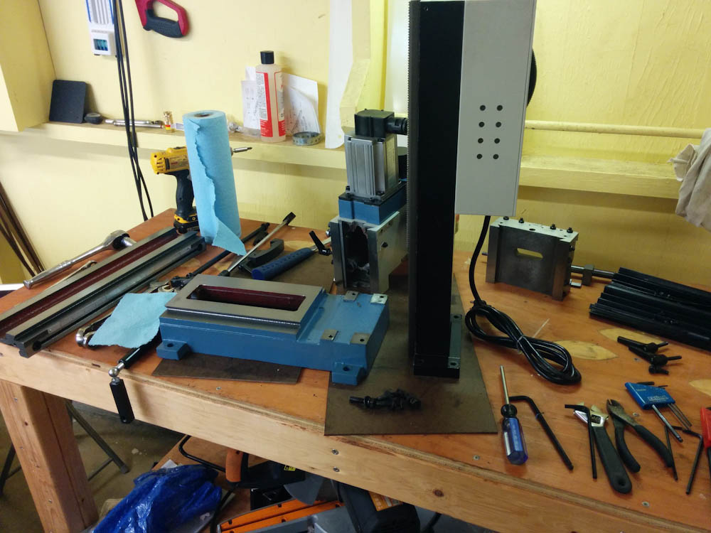
A mini mill, with CNC

As mentioned over the last few posts of the NC30 EFI project, I’m going to need to fabricate various little metal parts. That’s not something that I’ve had the capability of doing here. Back when I got the ShapeOko, I was hoping it was going to be able to do light aluminum work. While I managed to cut some parts out of a 1/4″ plate, it took forever and ended up with the end mill clogged with aluminum due to the low feed speed. The cuts were also not very good, the gantry setup is just too flexible to be able to do aluminum well enough to be useful.

So, over the past month or so I decided that I wanted to get something more capable. You can get super nice “benchtop” CNC mills like the Tormach PCNC 440 for something like 7 grand (ayour bench better be solid because it weighs 450lbs) plus shipping, tools, etc. That’s just a little bit more than I want to spend, though.

At the other end in price (and capability), you have the ubiquitous “Harbor Freight” Mini mill, for $650, available from 4 or 5 different suppliers that put their own nameplates on what is the same Chinese product. There exists a small cottage industry dedicated to improving, upgrading, and converting these mills to computer control. The $650 really only get you the basis for a project, where you have to add your own motors, ball screws, etc, to be able to control it. If you google on “mini mill CNC conversion”, there are literally thousands of posts and videos of people doing this. The problem is that the basic mill has a very small working area and is marred by some other basic flaws that need fixing or that limit the ultimate result.

As a step up, the people at LittleMachineShop.com have developed their own variant of the same mill, the HiTorque mill, that fixes some of the worst flaws of the basic model. For $250 more, you get a more rigid structure, larger table, and a better spindle motor. This is what I decided to get.

For the CNC conversion, the standard kit is the one from CNC Fusion, which includes ballscrews and ball nuts, bearings, motor mounts, etc. Then you also need the electronics. Since I feel more comfortable in this area I decided to assembly my own components here.

In the end, all the parts ended up somewhere around 2.5 grand, but this includes shipping and also the basic things you need to actually use the mill, like a vise, end mills, indicators, mounting hardware, etc. (If it’s 1/3 as capable as the Tormach remains to be seen…)

I didn’t take any pictures of the mill as it arrived in the crate, but there are enough pictures of it on the web anyway. The mill arrives completely covered in grease, like dripping with it, so first order of business is to clean all that off and then replace with a light coat of oil for rust protection. (I’ve had enough of my tools rust here in Hawaii that I’m super paranoid about wiping everything made out of metal down with 3-36 after use now.)

Here's the mill fully torn down for cleaning and installation of the CNC kit.

Here’s the mill fully torn down for cleaning and installation of the CNC kit.

The CNCFusion kit is mostly bolt-on (once you’ve removed the old lead screws and other stuff like hand wheels you don’t need on a CNC machine), but there are a few places where you have to make some modifications.

One thing you have to do is drill 4 holes in the top of the column for mounting the Z-axis motor mount. It seems most people do this by hand drilling, but given the need for reasonably accurate positioning I was not excited at the prospect of hand-drilling 4 5mm holes through roughly 20mm of cast iron. Since the mill was basically torn apart anyway, I removed the motor electronics box from the column so I could drill the holes in the drill press instead. This worked much better.

You're required to drill 4 holes in the column. Rather than trying to hand drill these holes through the ~20mm thick cast iron, I tore the mill down to the bare column and drilled it in the drill press and tapped them with M6 threads rather than use nuts.

You’re required to drill 4 holes in the column. Rather than trying to hand drill these holes through the ~20mm thick cast iron, I tore the mill down to the bare column and drilled it in the drill press and tapped them with M6 threads rather than use nuts. The tap was almost not long enough, I had to go all the way down to the point where the threads end to get the holes tapped all the way through.

Another modification needed is to remove some material from the base so the end of the Y-axis ball screw will fit. (If the ball screw was made shorter, you’d lose some Y-axis range, because the ball nut assemblies are much longer than the nuts used by the leads crews.) I did this with the Dremel, and it was shaping up to be a long and tedious job until I realized I had bought this high-quality 1/8″ carbide end mill specifically for steel. Since 1/8″ shanks fit in the Dremel, I tried using it and it sure cut a lot better than the other Dremel tools! It would have gone even better if the Dremel bearings were better, because if I tried to push the bit hard I got extreme chatter. Nevertheless, it probably didn’t take more than half an hour to get enough material removed.

One other modification that has to be done is to grind out a small piece of the base so the Y-axis ball screw will clear it. This was going to take forever with the Dremel, until I realized the 1/8" carbide end mill I had bought also fits in the Dremel...

One other modification that has to be done is to grind out a small piece of the base so the Y-axis ball screw will clear it. This was going to take forever with the Dremel, until I realized the 1/8″ carbide end mill I had bought also fits in the Dremel…

With those modifications out of the way, it was down to assembly and adjustment. This largely went OK. The assembled table looks like this.

The assembled table, complete with stepper motors. The column is still not mounted.

The assembled table, complete with stepper motors. The column is still not mounted.

I’ll save the electronics box for another post, but at this point I hooked up the motors and started running things back and forth to make sure everything ran smoothly. While it works, I’m having some issues with the ball screws not sitting square in the bearings. I don’t know if they are actually bent or if they’re just not seated right, but it makes it impossible to get them to roll smoothly all through the range. It appears I’m not the only one who’s had this problem, so I’m waiting for word back from CNCFusion as to whether this is a machining defect or if something can be done about it. Here’s a video showing what’s happening:

While this causes some binding of the ball screws that you can feel when turning them by hand, the stepper motors don’t seem to have a problem moving the axes. I worked my way up to some rapid moves that I recorded as well:

There are a few things that would be very good to have, like limit switches so I don’t accidentally run any of the axis into the end stops, and some sort of guard to protect the Z-axis ball screw from chips and other junk. I also need to hook up the spindle motor to the controller so it can be controlled from the G-code as well, but at this point it should be good enough to try some cuts.


Microsquirting the NC30, part #14: A CAD detour

Since the last post, the task has been to figure out how to mount all the fuel injection hardware. I decided that this was best done by computer modeling, since there are a bunch of different pieces of hardware that have to fit together correctly, without interference in the cramped space. The “V” engine also makes everything tilted and hard to visualize.

A while ago I got Cubify Design, the “hobbyist” version of a professional-grade CAD program (Geomagic Design). It was the only program I could find that had full parametric modeling capability for a reasonable price ($199). Parametric modeling means you can define your geometry in terms of relations between components, so that you can change the parameters and subsequent operations update automatically. It’s a very powerful way of modeling, which also means there’s quite a learning curve in using the program. I spent quite some time going through tutorials and doing little test projects.

So now it was time for the first “real” modeling task. I modeled up the airbox, the carburetors, and the rubber boots that hold them. This way I could deduce the 3D location of the intakes, which otherwise is hard to determine. I could then “freeze” the airbox and rubber boots in space, replace the carbs with the throttle bodies, and then I would be able to figure out the shape needed for the adapters that would hold them.

This worked quite well, and I actually got to a pretty reasonable result when I ran smack into an unexpected roadblock. I was unable to figure out how to export the model from Cubify in any other file format than “STL”, which is used to describe triangulated solids. This turned my round adapter barrel into a polygon!

After some frustration, I contacted Cubify support, who told me that, indeed, that is the only export option. If you want to export your model in a “real” file format, you obviously is a professional and you should buy the $1999 version instead! They are holding their users data hostage!

About this time, I got a tip from Marco, a fellow Long-Ez builder who, unlike me, is actually making progress on his airplane. (Check out his blog, it’s full of interesting stories related to plane building and workshop stuff in general!) He pointed out that Autodesk is pushing their new CAD program Fusion 360 hard, and it’s free for anyone making less than $100k from using it! Fusion 360 is pretty cool, it’s not just a CAD program, it has an advanced CAM functionality for manufacturing your parts using CNC machines, stress/strain modeling, making ray-traced renderings of your model, and much more. Pretty cool!

The combined CAD/CAM is a killer. Now you can design a fully 3-dimensional part and then generate the CNC program to machine it from within the same program, which is awesome.

So I decided to trash Cubify and start over learning Fusion 360. It’s not as well polished, because it’s a much newer program, and I kept getting hung up on things that were easy in Cubify but had some annoying quirks in Fusion 360. But I persevered!

Here's the throttle body assembly model complete with adapters, injectors, fuel rail, and some of the brackets that will hold the throttle bodies in position.

Here’s the throttle body assembly model complete with adapters, injectors, fuel rail, and some of the brackets that will hold the throttle bodies in position. The NC30 wizards out there may recognize that the sub air filter (the protrusion in the top black plastic piece) is on the wrong side. Yes, I managed to model that part mirror-flipped…

This image shows the model right now. The shiny parts are the ones that will be manufactured: the throttle body adapters, the fuel rails, and brackets holding them.

The throttle body adapter. This will be machined out of a piece of Aluminum.

The throttle body adapter. This will be machined out of a piece of Aluminum.

The adapter turned out to be quite simple. As you can see, it’s the same diameter as the throttle body, so I’ll mount them with a short length of silicone hose over the outside.

The fuel rail turned out to be a bit tricky. I had planned to use extruded fuel rail stock from Ross Machine Racing, but it turns out there’s so little space under the airbox that I had to resort to a more custom solution. SDS has a tips page talking about how to build a fuel rail, using 3/4″ square tubing. It’s preferable to use steel or even stainless due to its lower thermal conductivity as it will heat the fuel up less, but given the difficulty of machining I’m going to go with 6061.

The fuel rail and one of the brackets that hold it to the throttle bodies. The injector will be held by a small square piece of 6061 that has been bored to the proper diameter and mounted in a cutout in the square tube.

The fuel rail and one of the brackets that hold it to the throttle bodies. The injector will be held by a small square piece of 6061 that has been bored to the proper diameter and mounted in a cutout in the square tube. The small cutout in the bottom part prevents the injector from rotating. (This is an example of Fusion 360’s ray tracing capability.)

In most cases, people use a round “boss” that the top of the injector sticks into, and this is then welded to the fuel rail. The problem with this is that the fuel rail sticks up far above the top of the injectors, and there just isn’t enough room for that. So instead, my injector bosses will be welded into cutouts in the square tube. This cuts down on the cross sectional area somewhat, but there should be plenty of area for the fuel to flow through. I’ll also have to bore out the injector mounting holes in the throttle bodies a bit, I discovered that they aren’t quite deep enough right now. That also gets the injectors about 5mm lower, which helps.

The fuel rails will be held in the correct position with brackets machined out of 1/2″ thick Aluminum. The brackets completely surround the square tube and are held with bolts that screw into the existing holes in the throttle body that were used for that purpose with the stock injectors.

I’ve been a bit nervous ever since I realized how little space there is under the airbox, but I think this model shows that it’s going to work out. However, there’s a bunch of parts that will need to be fabricated. I’m getting set up to do that, too, but more on that later.


Microsquirting the NC30, part #13: Out with the old…

The carbs are out. The only way they ever get to flow some gas on this bike again is if I admit defeat with this whole project.

With the carbs out, I got my first chance to see how throttle bodies I got on ebay would fit. They are from a Kawasaki GPz1100 B2 from 1982 (imagine, 10 years older than the NC30 and with electronic fuel injection) and I knew from this page that they had a bore of 34mm, roughly similar to the NC30 carbs.

That size is somewhat surprising given that they came off of a bike with almost three times the displacement, but I think they used throttle bodies that were comparatively undersized by today’s standards at the time. Since they don’t have any vacuum slides or anything in them, I suspect they had to keep the bore down to get the response to small throttle openings to be reasonable. As a comparison, modern 600cc sport bikes use throttle bodies with bores in the 38-40mm range, but they are complicated beasts with staged injectors and they also usually have vacuum slides to prevent the low-throttle response from being too abrupt.

The GPz1100 throttle body on the left vs the NC30 carb on the right. The bore and general size are pretty close.

The GPz1100 throttle body on the left vs the NC30 carb on the right. The bore and general size are pretty close.

As you can see in the picture, the general size of the throttle body is pretty close to that of the carbs, although the throttle body of course is much slimmer due to the lack of float bowl and slide diaphragm. It’s quite a bit shorter, so this is where some sort of adapter will have to be manufactured to fit it to the airbox.

I was pleased to discover that the throttle bodies actually fit directly in the stock rubber mounts. They're a tad too large, but that can easily be fixed.

I was pleased to discover that the throttle bodies actually fit directly in the stock rubber mounts. They’re a tad too large, but that can easily be fixed. The only problem immediately noticed is that there’s not enough space for the throttle position sensor between cylinder 4 and the right side of the frame. (For reference, the center distance between the two intakes is 127.5mm.)

Amazingly, they even fit directly in the stock rubber boots! Some minor adjustment will have to be made, because they have a raised ridge around the end that aren’t on the carbs and make them slightly large, but that should be an easy fix. The real tasks will be to make the throttle linkage work between the front and rear pair and to mount them to the airbox.

This is the airbox bottom that the throttle bodies will need to mount to. The carbs are hard-mounted to this bracket.

This is the airbox bottom that the throttle bodies will need to mount to. The carbs are hard-mounted to this bracket.

The airbox bottom has a rubber trumpet for each carb, the base of which also functions as a gasket to seal the connection to the carburetor, which has a machined groove to mate with a raised ridge on the rubber trumpet.

This is where the carb mounts to the airbox. The groove is where a ridge on the rubber trumpet makes a seal. A similar adapter plate will need to be manufactured for each of the throttle bodies.

This is where the carb mounts to the airbox. The groove is where a ridge on the rubber trumpet makes a seal. A similar adapter plate will need to be manufactured for each of the throttle bodies.

This pattern is what I have to match up, a groove and two bolt holes with guide pins. It will take some moderate precision manufacturing to get this to work. As you can see in the top picture, the airbox side of the throttle body is a flat cylinder. They must have originally used a rubber mount also on the airbox side. It will probably be easiest to use the same pattern, to make an adapter plate that screws into the airbox and has a similar diameter as the throttle body such that a rubber connecting pipe can be mounted between the two. This will also make the alignment slightly less critical than if I try to hard-mount the throttle bodies to the adapter plates.

Microsquirting the NC30, part #12: Timing measurement

In the last post, I had loaded up the bike with a simple timing curve and taken it for a test ride. However, I have been meaning to actually measure the timing advance with the stock ignition unit rather than relying on hearsay. This weekend I finally press-ganged Kathy into helping.

When I previously had attempted to measure the timing at anything higher than idle, I had gotten my face sprayed with oil being blown out of the hole you open up to see the timing marks. The air in the crankcase gets pushed out when the pistons go down, and while this normally gets vented into the airbox, the air likes to take the path of least resistance and prefers to go out this hole when given the chance. First order of business was thus to manufacture a “window” of plexiglas that could be put over the hole to avoid this problem.

The window worked surprisingly well, I duct taped it to the crankcase and it held up almost half the session… Once the engine got hot and the oil started trickling out the hole, the duct tape quickly turned into something resembling used chewing gum and I had to resort to holding the window in place with my fingers. Which was fine except that once the engine’s hot it was hard to do for a long time, even with welding gloves.

Anyway, Kathy had the responsibility of revving the engine to the requested RPM and writing down the data. I handled the timing light and holding the window in place. It didn’t take long until we had some decent data:

The ignition advance as a function of RPM as measured with the stock ignition unit. My points are in blue and the corresponding measurement by user "whizzo944" at 400greybike.com is in green. Interestingly the wiggle at 4k RPM appears to be real, as it shows up in both sets of data.

The ignition advance as a function of RPM as measured with the stock ignition unit. My points are in blue and the corresponding measurement by user “whizzo944” at 400greybike.com is in green. Interestingly the wiggle at 4k RPM appears to be real, as it shows up in both sets of data.

The plot also has overlaid points from a plot I got from “whizzo944” at the 400greybike forums. There are some systematic differences, but the behavior is quite similar. In particular, we both have a peak and subsequent drop at 4k, and then a drop between 7-12k (although we only measured 13k because it’s so painful to rev the bike that high). The slight retard between 8-12k isn’t so surprising, since that’s where the torque peak is; engines often need a bit of retarded timing in that region, because that’s where the cylinder filling is the highest. I’m not sure what’s going on with the dip at 4k though.

The striking difference between these curves and the “linear between 2-12k” that I used in the first test drive is how fast this curve advances. This should make quite a bit of difference in the amount of low-end power. Naturally, I had to take it for another test ride.

It did indeed feel like it had a lot better low-end torque, and it also ran less hot than last time, which would make sense since retarded timing puts a lot more heat out in the exhaust port that is never converted to mechanical power. However, when I did a full-throttle test in high gear from very low RPM, it was pretty clear that there is a severe flat spot in the 5-6k RPM region, and just under 6k I also heard something that sounded very much like knocking. Had I put in too much advance at low RPM?

Zooming in on that full-throttle run in the data log, it looks like this (click on the plot to see it in full res):

The full-throttle run. You may have to zoom in to see the points clearly. The left plot shows RPM as a function of time, clearly showing the "flat spot" between 5-6k RPM. The plot on the right is lambda as a function of RPM. The regions of slow acceleation on the left clearly coincide with the bike running so rich it saturates the wideband sensor at lambda 0.68.

The full-throttle run. You may have to zoom in to see the points clearly. The left plot shows RPM as a function of time, clearly showing the “flat spot” between 5-6k RPM. The plot on the right is lambda as a function of RPM. The regions of slow acceleration on the left clearly coincide with the bike running so rich it saturates the wideband sensor at lambda 0.68.

The data log makes it clear that the regions where the bike accelerates really poorly, at 3k and 5-6k RPM, are exactly where the oxygen sensor shows it running so rich it actually saturates the wideband sensor, meaning lamda < 0.68! (That’s an air/fuel ratio less than 10:1 for those of you who don’t like to think in lambda.) The thing I heard that sounded like knocking was more likely the engine misfiring from being so rich. Once above 6k, it starts pulling comparatively well, and there the lambda is “only” 0.77-0.80. As I said before, once it’s possible to dial in a reasonable air/fuel ratio, it should run way better.

Speaking of that, I think this means the ignition part of the project (the “easy” part…) is pretty much complete. Now it’s time to take the carburetors out and figure out how to mount the throttle bodies and the fuel injectors.

Microsquirting the NC30, part #11: Crank trigger

After getting the spark hardware hooked up, it was time to get the Microsquirt to know about crankshaft motion. As I mentioned in the last post, the motor has two “pulse generator” coils offset from each other. My hope was that the signal from these coils could be hooked up as-is, since this is a sort-of standard sensor type and the “8 teeth with one missing” pattern is readily settable with the Microsquirt. The one problem with 8 teeth might be that it forces the ECU to extrapolate up to 45 degrees into the future, so if crankshaft speed changes during the rotation, the ignition timing might be a bit inaccurate. For this reason, it is recommended to use at least 12-16 teeth on a high-revving engine like a motorcycle. (For a car, 60 teeth is the standard.)

This is the output from one of the pulse coils. There are 7 peaks, and then one missing where the eighth one should have been.

This is the output from one of the pulse coils. There are 7 peaks, and then one missing where the eighth one should have been.

As can be seen in the oscilloscope picture above, the signal is about +-20V with very sharp transitions going low to high. These sharp transitions happen when the tooth is passing by the coil, while the flat transition going the other way is when the teeth are midway. (It’s important to get the polarity right here, if the Microsquirt is looking for a transition going low, it’ll pick up the very indistinct midway-between points and nothing will work right.)

It was pretty quick to hook one of the coils up to the Microsquirt inputs and set up the trigger type, and when I tried cranking the engine (with no gas in it) I was immediately rewarded with a fairly stable rpm reading. The software will alert you to any “sync loss” which happens if it can’t detect the missing tooth or if the signals are very uneven, and this looked perfect. The tooth log below looked exactly as it should.

This shows the "Tooth log" output from the Microsquirt. Each bar is a tooth signal, and the height is proportional to the time between it and the previous tooth. The "8-1" tooth pattern shows up as 6 bars and then one with twice the height. The slight variation in bar height is because the crankshaft speed slows down on compression strokes and speeds up when combustion happens.

This shows the “Tooth log” output from the Microsquirt. Each bar is a tooth signal, and the height is proportional to the time between it and the previous tooth. The “8-1” tooth pattern shows up as 6 bars and then one with twice the height. The slight variation in bar height is because the crankshaft speed slows down on compression strokes and speeds up when combustion happens. (This is actually with the engine idling, not cranking.)

The next step is to physically verify that the crankshaft is where you think it is using a timing light. Setting ignition angle to 0 (at TDC), the timing light should show cylinder #1 at TDC, and it did. Since this engine has uneven firing order, I thought it prudent to also verify that the spark for cylinder #2 went off when it was at TDC, which it also did. Time to see if it would start. For the moment, I set timing to a constant 18 degrees BTDC which is the factory-specified idle timing.

After putting the tank back on and cranking a little to fill the carbs with gas, it started uneventfully and idled quite nicely. Verifying timing again, now with the engine running, still showed cylinder #1 dead on and cylinder #2 maybe a degree off from the timing mark. This was almost going too well…

The first setback happened when I gave it some gas. It basically refused to rev much above idle, making a sound like a rev limiter was in effect. The log also showed numerous sync loss events and now the tooth log looked like this:

This is the tooth log trying to give it some gas. The nice long-bar sync pattern is replaced with a shorter bar instead, which is what you'd expect if it was picking up the little peak associated with the missing tooth.

This is the tooth log trying to give it some gas. The nice long-bar sync pattern is replaced with a shorter bar instead, which is what you’d expect if it was picking up the little peak associated with the missing tooth.

Turns out this is not an entirely uncommon situation. The issue is that when the engine speed increases, the voltage output from the coils increase to the point that the tiny little peak associated with the missing tooth in the scope trace above gets picked up as a real tooth. The solution suggested is to put a resistor across the coil to reduce its output voltage, and sure enough, with a 1k resistor the problem went away and I was rewarded with a clean rev without sync loss. It wouldn’t go past 10k RPM, but since the timing was fixed at 18 degrees that’s not unexpected.

Before I could go on a test ride, I would need a more realistic ignition timing curve at higher RPM. The factory manual specifies that timing start to advance from 18 degrees at 1800RPM and reaches max advance of 37 degrees at 12000RPM. The simplest thing to do was to just assume a linear advance between those two points. (I still want to measure the timing curve with the stock ignition unit, but that’s a bit complicated so I haven’t gotten around to it yet.)

With that curve set, I took it for a test ride. It runs pretty much the same, except that I got a very noticeable knock at full throttle around 7-8k RPM! This is a bit surprising. One possibility is that the ignition curve actually advances more slowly through this region, such that my timing is too far advanced. The other possibility is that my timing is off at high RPM (and perhaps high loads. It seems likely the crankshaft speed is most uneven at full throttle, when the combustion events have more torque.)

I don’t think the timing should be that off, because the position of the teeth are such that “tooth #1” (the one after the missing one) is detected 126 degrees BTDC. Since there is a tooth every 45 degrees, that means tooth #3 passes at 34 degrees. For advances less than this, the Microsquirt only have to extrapolate from 34 degrees down to whatever the advance is, so it seems that should be reasonably accurate. For very high RPM, when the advance becomes greater than 34 degrees, though, it has to go almost the full 45 degrees from the earlier tooth, so that might be more of an issue. Since the two cylinders are 90 degrees apart, this reasoning holds for both cylinder pairs.

I guess the first thing to do is to actually measure the timing at higher RPM than idle. More on that next.


Microsquirting the NC30, part #10: Spark hardware

As of the last post, the bike was running with all sensors functional and it was time to make the Microsquirt finally do something useful: control the ignition. To understand the setup, we have to go into some amount of detail.

The way (most) ignition systems work is using an ignition coil, which has two windings, a primary, with few turns, and a secondary, with many. The coil is “charged” by running a current through the primary winding. When this current is suddenly interrupted, the rapid change in the magnetic field induces a very high voltage in the secondary winding, which is attached to the spark plugs.

In ye old days, the coil current was started and interrupted by mechanical “points” on a distributor, but these days it is electronically controlled with a semiconductor “switch” instead. This makes it possible to adjust the ignition timing based on all kinds of various variables that wasn’t possible (or at least very difficult) with a mechanical system.

The stock ignition system on the NC30 is electronic. There are two ignition coils, one each for the front and rear pairs. These are hooked up in what’s known as “wasted spark” mode, meaning both ends of the coil winding are connected to a spark plug, so firing the coil fires both spark plugs at the same time. This works because the NC30 has a “360-degree crank”, shown below on a picture shamelessly stolen from someone on the internet.

The NC30’s “360-degree crank”. The engine is like two identical V-twins, side by side.

Each crank throw is connected to one front and one rear piston, so the engine effectively is like two identical V-twin engines mounted side by side. This means that when one front cylinder is between the compression and combustion stroke, ready to fire, the other is “360 degrees” (hence the name) away in the 720-degree 4-stroke combustion cycle. This puts it between the exhaust and intake stroke, so the cylinder is empty and has no burnable fuel in it. Hence, it doesn’t matter if that spark plug fires at the same time, it is just “wasted”, hence the name. The same applies to the rear cylinders.

This design means that we can get away with only two ignition coils even though we have 4 cylinders (which is good because the Microsquirt can by default only drive 2 ignition outputs) and it also means the engine controller doesn’t have to know where in the combustion cycle the engine is, since one of the two cylinders will fire every revolution. This saves us from needing to sense the camshaft position, further simplifying the ignition setup.

The stock ignition unit senses the crankshaft position using a pair of “pulse generator” coils mounted around the crankshaft. These coils pick up the passage of “teeth” on the starter clutch wheel, sending a signal to the ignition unit. The wheel has 8 teeth, i.e., one every 45 degrees, but one of them is missing. The missing tooth makes it possible to know where in the revolution the crankshaft is. The two coils are offset by about 72 degrees, effectively giving a 16-tooth resolution. 72 is 45+27, so the signals from one coil are pretty much halfway between those from the other, effectively doubling the resolution. (As well as making it possible to tell which direction the crankshaft is going in, but that should hopefully never be necessary…)

This ignition unit also contains the electronic “switches” used to turn the ignition coils on and off, so removing it means something else has to fulfill that function. The Microsquirt itself doesn’t have the ability to switch the high coil current, so this must be done by an external component, in my case a Bosch ignition module that I got on ebay. First order of business was to mount that somewhere.

The rectifier will be moved from the stock location on the left (where it's really too large to fit) to this new bracket made out of 1/8" aluminum.

The rectifier will be moved from the stock location on the left (where it’s really too large to fit) to this new bracket made out of 1/8″ aluminum.

As I started looking for places to put the ignition module, I decided I should just go ahead and move the regulator as well. Back when I did the regulator upgrade, I shoehorned this in where the old one had been mounted, but it really didn’t fit well there. Every time I’ve taken the fairing off, I’ve had to bend it to go around the new, larger, rectifier, so since I was going to have to make some mounting bracket anyway, why not move the rectifier to a better place, too?

Moving backwards from the old location (on the left in the picture above), the fairing is much wider and there’s a lot more space, so I decided to make a sturdy aluminum bracket and attach it to the bolts that hold the muffler hanger. By welding a piece on top, I could then attach it to the top part of the subframe, too, and it would be really sturdy.

The new mounting for the rectifier worked out really well. Until, that is, I tried to put the fairing back on...

The new mounting for the rectifier worked out really well. Until, that is, I tried to put the fairing back on…

The fabrication of this piece went well, until I had mounted the rectifier on it and tried to put the fairing back on and had it hit the top of the rectifier! I’m not sure how this happened, I trial fit the fairing on numerous times. The only thing I can imagine is that it actually had hung up on something and wasn’t seated right, so I incorrectly thought I had more room than I really had.

The real problem with this is that the rectifier can’t move down, the bolts holding the exhaust hanger are in the way. I tried grinding off the top of the rectifier heatsink (it doesn’t really get warm at all) which helped but not nearly enough. After being upset with myself for a while I realized that the way to get it to fit was to tilt it forward. It looks kind of bad, but a least it fits.

With that problem solved, I could now mount the ignition module, which is much smaller than the rectifier, where the rectifier used to be. It needs a flat surface for thermal conduction, so I had to make sure the remains of the rectifier studs were all ground down, but then it fit without a hitch.

The  new ignition module mounted where the rectifier used to be, and the rectifier in the rotated position where it clears the fairing. It doesn't look very good, but it's not visible from the outside.

The new ignition module mounted where the rectifier used to be, and the rectifier in the rotated position where it clears the fairing. It doesn’t look very good, but it’s not visible from the outside.

This picture illustrates how little space there is between the top of the fairing and the rectifier. The ignition module, by comparison, has tons of space.

This picture illustrates how little space there is between the top of the fairing and the rectifier. The ignition module, by comparison, has tons of space.

With the hardware mounted, all that remained was to wire it up. Two wires go to the Microsquirt ignition outputs, and then I hooked the outputs up to the same connector the stock ignition unit was connected to. This way it’s easy to swap back and forth between the old unit and the Microsquirt, which I bet will be useful during the test phase.

With this wiring completed, I fired up the laptop and put the Microsquirt into “spark test mode”, where you can fire each of the ignition coils with different parameters, and it worked perfectly.

Next order of business is to hook it up to the pulse coils on the crankshaft.

Microsquirting the NC30, part #9: Some debugging

Finally, it was time to go for a test ride. You can view and log data over Bluetooth with a phone using the MSdroid Android app. Going out for a ride, everything seemed good until the RPM gauge spiked to 10k and then back down. Uh oh — this is what the Atmega does when it boots, so this was an indication that it had rebooted “in flight”. That’s not supposed to happen. A few moments later, the RPM gauge started going totally nuts, bouncing between 10k and max, down to zero, jumping around randomly, and then dying.

This is the most frustrating part about programming an Arduino — you can’t just run it in the debugger and see what’s happening. I commented out various parts of the code to see if I could isolate what was causing it, but it seemed semi-random. By going over the code with a fine-toothed comb, sure enough, I found one instance of a forgotten “&”, hence using the value of a variable, rather than its address, as a pointer. I also found another place with flawed logic that could lead to writing to random places in memory. But even after fixing this, the problems remained. I didn’t get the random behavior of the RPM gauge anymore, but it would still reboot.

Looking at the logs, it was interesting to note that sometimes the Bluetooth connection to the Microsquirt was interrupted at the same time the . That’s a totally separate circuit, the only common part between the bluetooth modem and the microcontroller is … the power supply!

This shouldn’t be a big surprise, actually, automotive power is notoriously noisy, and this is an area that I don’t know that much about. If the power circuitry didn’t properly insulate the microcontroller from various transients, that could easily be causing the problems. To test this theory, I went for a spin with the alternator unplugged. Sure enough, the problem went away.

Ok, time to rip up the electronics box again. I’m getting quite skilled at it, though.

The conversion from 12V to 5V is done by a tiny MIC5205 voltage regulator on the circuit board OshPark made for me. It’s specced for 150mA, and the Atmega, CAN-bus controller, transceiver and the Bluetooth modem all use no more than 70mA. Sounds fine, right? Not quite. The maximum current is one limit, but it turns out that most often, the max current output is limited by the maximum power dissipation.

Linear voltage regulators change an input voltage to a lower output voltage by essentially converting the excess power to heat. This means that the regulator will dissipate a power equal to the current passing through it times the voltage drop, V_in-V_out. The limiting factor is the maximum temperature of the silicon junction, so how much power can be passed through it depends on how efficiently heat can be transported away. (This is why it helps to put heat sinks on stuff…)

Well, it turns out that using the thermal resistance quoted by the datasheet, when supplying 70mA the regulator will overheat when the output-input voltage difference is maybe 3-4V (depending on the ambient temperature). That would be an input voltage of 8-9V, when in reality it is being fed 12V with the engine off and up to 15V when running! There’s no way it can handle that much power, and when it overheats, it will go into thermal shutdown. No wonder I’ve been having problems!

So, I pulled the circuit board out and thought about what to do. The obvious solution is to add a pre-regulator that will take the 12-15V down to <8V that the MIC5205 can handle. I happen to have a box of LM317 regulators. Those are big (TO-220 case) and can handle a lot more power. The only hitch is that they are adjustable and require some extra components, so it wasn’t so easy to add it onto the existing circuit, but it worked out. Here’s what I ended up with:

This is the newly added LM317 voltage regulator, sitting between the headers that the circuit board with the CAN controller fits into. It's almost half the size of that entire board... The resistor soldered across the pins in part of the voltage dicider that sets the output voltage. Also added was the 47uF capacitor immediately to the left.

This is the newly added LM317 voltage regulator, sitting between the headers that the circuit board with the CAN controller fits into. It’s almost half the size of that entire board… The resistor soldered across the pins in part of the voltage divider that sets the output voltage. Also added was the 47uF capacitor immediately to the left.

As you can see, the LM317 ended up fitting nicely under the CAN controller circuit board. If you look hard, you can see the 12V supply trace on the back side has been cut, and routed through the input and output pins on the LM317 (on the right and center, respectively.)

Here's where it gets ugly. A bunch of components were added to the back side of the board.

Here’s where it gets ugly. A bunch of components were added to the back side of the board.

To set the output voltage, you need two resistors. The first is soldered between the output and adjustment pins right next to the case. The second is on the back of the board and goes to ground (the 2.7k resistor on the right in the picture above.) The tan square is the 4.7uF capacitor for the LM317 regulator input.

While I was adding stuff, I decided to add a diode (the small black component) that prevents this circuit from being pulled down if there is a transient low-voltage event. The glass component is a 20V zener diode that protects against transient overvoltages (and reverse voltages) by shunting those to ground, and the 10 Ohm resistor will limit the current that needs to be shunted in those cases. It also forms an RC low-pass filter with the capacitor, but its time constant is 50us so it will only help against high-frequency noise.

On the LM317 output, I added a bigger 47uF capacitor, which in principle will be able to supply the 70mA current for half a millisecond.

While it’s certainly not improving the increasingly ghetto-looking circuit board, it actually worked pretty OK to add the components across the traces. Now I’m happy I made those traces as wide as I did!

Testing the new circuit, the MIC5205 seems a lot happier. When I ran it on 12V before, you’d burn your finger touching it. Now it’s not noticeably hot, and the LM317 was warm-ish to the touch, even with 15V input. Seems pretty promising.

After mounting all the circuit boards into the box again (did I mention I’m getting good at it?), I went for another test drive.

Flawless!

This is an example of what the data look like. The axes are manifold pressure and lambda, with RPM being the color scale. As suspected, the bike runs really rich, typically around lambda 0.8, and it even saturates the wideband sensor at 0.69 lambda a significant part of the time at full throttle.

This is an example of what the data look like. The axes are manifold pressure and lambda, with RPM being the color scale. As suspected, the bike runs really rich, typically around lambda 0.8, and it even saturates the wideband sensor at 0.69 lambda a significant part of the time at full throttle.

Over 20 minutes, there was not a single hickup. Clearly that meant problem solved, so I immediately went for a ride up the Saddle Road all the way up to the Mauna Kea visitor station at 9200 feet. (I wanted to get data on how what the air/fuel ratios with the carburetors were all the way up there before starting to change things.) Above is an excerpt of the logged data.

As expected, the bike is running rich. Very rich. The plot above is near sea level and shows lambda (air/fuel ratio in relation to the ideal 14.7) against manifold pressure, essentially throttle opening. It appears to run at about lambda 0.8 for partial throttle, and the full-throttle lambda goes all the way down to 0.69 which is as rich as the SLC lambda controller reports!

As you might expect, this got worse at altitude. (Carburetors meter fuel against air volume, not mass, so as air density decreases, they run richer and richer.) Going up the final 2000ft, the lambdas were often pegged at the 0.69 limit. The bike runs really poorly at that altitude, and I guess that’s not a surprise.

For reference, maximum power for a gasoline engine occurs at about a lambda of 0.86. At full throttle, you might need to go a bit richer than that, maybe to 0.82, to prevent the engine from knocking. But running at 0.7 would not only make much worse power, it would also make the exhaust really sooty (check) and smelly from vastly increased hydrocarbon emissions (check). Not to mention waste gas. The two cylinder pairs also run at noticeably different lambdas. I think there is plenty of room for improvement here! 😉

Now that I know the sensors are working, the next step is to pull out the stock ignition module and get the Microsquirt to handle the ignition.

Microsquirting the NC30, part #8: The tachometer

I was feeling pretty good about how things were going when I “just” had hooking up the tachometer left. That’s when I ran into an unsolved problem. From looking at the tachometer signal with the oscilloscope, I had determined that it consisted of short, square pulses, 4 per engine revolution. The Microsquirt outputs a tachometer signal, but it outputs one pulse per cylinder per engine cycle, i.e. per 2 revolutions. There is no way to configure it to output a higher frequency.

Another problem was that the signal to the tach was 7V, not 12V. And more strangely, if I unplugged the tach itself, the signal stopped even though the engine was still running. I realized this meant the stock ignition box must sink an output from the tach. Sure enough, the tach input showed 7V when unplugged.

This meant I could at least test it. While the “normal” Microsquirt tach output is a +12V pulsed signal, you can reroute the signal to one of the open-drain outputs. After doing this, the tach did indeed respond but, as suspected, it showed only half the RPM. Luckily the fact that the Microsquirt tach output is a 50/50 high/low square wave did not seem to affect how the tach responded to it.

I toyed with the option of building a pulse-doubling circuit, but realized that I have an unused pin in the connector to the wideband controller/comm box. The Atmega microcontroller that sends the oxygen sensor data to the CAN-bus can easily generate a pulse train with arbitrary frequency using the built-in timers. And it is also possible to request the RPM (or any other piece of data, in fact) over the CAN-bus. This sounds like a perfect solution.

There’s one small problem, though. The Arduino pins can’t handle 7V, and they can’t be switched between low and high-impedance using the timer, so an external MOSFET would be necessary. This was a bit annoying, since it meant the circuit board had to come out of the box…

The formerly professionally-looking circuit board is starting to slum it. I soldered a small MOSFET I had in on hand to ground and the timer output pin, and added a short lead to the drain pin.

The formerly professionally-looking circuit board is starting to slum it. I soldered a small MOSFET I had in on hand to ground and the timer output pin, and added a short lead to the drain pin.

The packaging will have to be done again, but it wasn’t that big of a deal. I connected a MOSFET to the timer output pin and ground on the circuit board with the Atmega and brought the drain pin out to a lead. When the Arduino pin is high, it’ll sink the tach voltage, when the pin is low, it’ll be disconnected. Piece of cake.

The other end of the lead connects to the unused pin on the Ampseal connector. Not too bad, this is what happens when you work with prototypes...

The other end of the lead connects to the unused pin on the Ampseal connector. Not too bad, this is what happens when you work with prototypes…

With the hardware worked out, I had to improve the software on the Atmega a bit. The Megasquirt CAN-bus protocol description at http://www.msextra.com/manuals/ details the different messages and how to send a request to the Microsquirt to respond with the RPM. Amazingly, it worked (almost) right away!

With the RPM in hand, it was not a big deal to set up Timer1 on the Atmega such that it toggles the output pin every time it reaches the set limit, and calculate what that limit should be for a given RPM. I had some glitches in the tach response until I realized that I should only change the timer limit from the interrupt that fires when the timer hits the limit. This prevents a scenario where, if you are setting a lower timer limit, the timer may already have ticked past the new limit and must then overflow the 16-bit register and wrap around before it hits the limit again.

I also noticed that the tach is noticeably nonlinear. It starts out showing about 500RPM less than the input frequency just above idle but by the time you get to 10,000RPM, it’s showing almost 1000RPM too much. That’s not a big deal, I fit a second order polynomial correction to “correct” the output frequency. I also discovered that the tach has noticeable hysteresis; the displayed RPM for, say, 7000RPM is quite different depending on whether you approach it from below or above. I guess this means that there’s some friction in the mechanism. It’s only maybe 400RPM, though. Not a huge deal.

So that’s where we’re at now. I’m pretty happy with the progress over the weekend. I still have to package the circuit board and the wideband controllers back into the enclosure and run the tach wire, but then I think it might finally be time to put it back together (at least the important parts like the gas tank) and go for a ride to see what happens with the engine under load.

Microsquirting the NC30, part #7: Reading lambda

Since the last post, the oxygen sensors are functional! While I had tested the controller boards when I initially built them, they’ve been sitting around since then. Now it was time to pack them into the box.

The two wideband controller boards on their way to being stacked into the box.

The two wideband controller boards on their way to being stacked into the box.

It was quite fiddly getting all the wires in place, but eventually it all got stacked up and aligned.

The controller boards in their mounted position.

The controller boards in their mounted position.

After plugging them in and adding all the fuses, it was time to try starting it! This presents a bit of a chicken-and-the-egg problem because, at the moment, the stock ignition is connected to the Microsquirt-switched power, which won’t be on unless it detects that the engine is at least cranking. The problem is that I’ve hooked the Microsquirt crank sensor input to the ignition coil, which makes it possible to at least detect a basic rpm signal, but the ignition coils aren’t powered unless the Microsquirt thinks the engine is running…

The solution, for now, is to start the engine immediately after turning the key on. The switched power will be on for 2s as the Microsquirt boots (so the fuel pump can bring the fuel system up to pressure), so as long as it detects that the engine is cranking within that time, it will allow it to continue running. Kind of ghetto, but fine for now.

So I poured some gas into the carbs and tried it. Nothing. Maybe it needs a bit more cranking? Nothing. Ah — it probably works better with the fuse for the ignition coils in place… After adding that, cranked again and was greeted by an epic backfire, with a shower of sparks coming out the muffler! Apparently, I didn’t really need to crank that long…

When I tried again, it started fine, and I quickly started getting data from the two oxygen sensors. First I thought it was idling epically rich, at lambda 0.75 or so, until I realized that I hadn’t actually set up the O2 sensor calibration. Actually, it appears to idle slightly lean (although that could also be all the misfires…) Revving it up to 3-4000 RPM gives much more stable lambdas, slightly on the rich side.

The wideband controllers also send the O2 sensor temperature to the Microsquirt, so I could also see them very quickly get up to 780C and stay pretty much rock solid there. Nice.

I realized there’s one more thing I needed to hook up now: the tachometer. That’s the next post.


Microsquirting the NC30, part #6: It’s alive!

All that remained before we’d have the Microsquirt alive when the last post ended was to plug everything into the connector… only there was a small setback.

The minimal test was to only wire up the power and the serial lines and make sure that we could talk to it over the Bluetooth modem. Except when I did, I got nothing.

After some troubleshooting with the scope, I concluded that transmission from the laptop to the Microsquirt made it fine through the bluetooth modem and the RS-232 transceiver. Nothing came back, however. And looking at the circuit board, I suddenly noticed…

This is where the RS-232 tranceiver breakout board is plugged in. Notice something funny?

This is where the RS-232 tranceiver breakout board is plugged in. Notice something funny with the traces?

In the picture, note how there are traces going to “T1IN” and “T1OUT” (that’s the transmitter 1 input and output) and “R2IN” and “R1OUT”… Whoops. The board has 2 transmitters and 2 receivers, and apparently I had wired up the inputs and outputs to different recievers. That certainly explains why nothing was coming back.

I think I know what happened here. My custom-made EAGLE symbol for the breakout board had the inputs on one side and the outputs on the other, but I never bothered to line up the two inputs with the corresponding outputs. So when I made the connections, I must have just connected the pins that lined up, without verifying the labels.

Oh well. While annoying, it’s easy to fix.

Problem solved. After this change, the communication worked perfectly.

Problem solved. After this change, the communication worked perfectly.

With that, the Microsquirt connected up to the tuner software on the laptop fine, so I proceeded to wire up the remaining connections.

After connecting all remaining wires to the appropriate pins on the 35-pin connector, it's getting quite crowded in that little space.

After connecting all remaining wires to the appropriate pins on the 35-pin connector, it’s getting quite crowded in that little space.

After entering the correct calibration constants for the pressure and temperature sensors, I now have sane-looking sensor readouts.

Both pressures and temperatures look reasonable.

Both pressures and temperatures look reasonable.

The manifold and ambient pressure reads 99kPa (the weather station says the current pressure is 99.8kPa) and the coolant and intake (not shown) temperatures were 29C. Seems satisfactory.

I also verified that the control of the radiator fan works by telling it to turn on at 25C. This did indeed turn the fan on.

The only remaining thing to wire up is to connect the oxygen sensor wires to the wideband controllers. I didn’t want to cut those wires until I knew what things were going to look like, but now the time for that has come too.