All that remained before we’d have the Microsquirt alive when the last post ended was to plug everything into the connector… only there was a small setback.
The minimal test was to only wire up the power and the serial lines and make sure that we could talk to it over the Bluetooth modem. Except when I did, I got nothing.
After some troubleshooting with the scope, I concluded that transmission from the laptop to the Microsquirt made it fine through the bluetooth modem and the RS-232 transceiver. Nothing came back, however. And looking at the circuit board, I suddenly noticed…
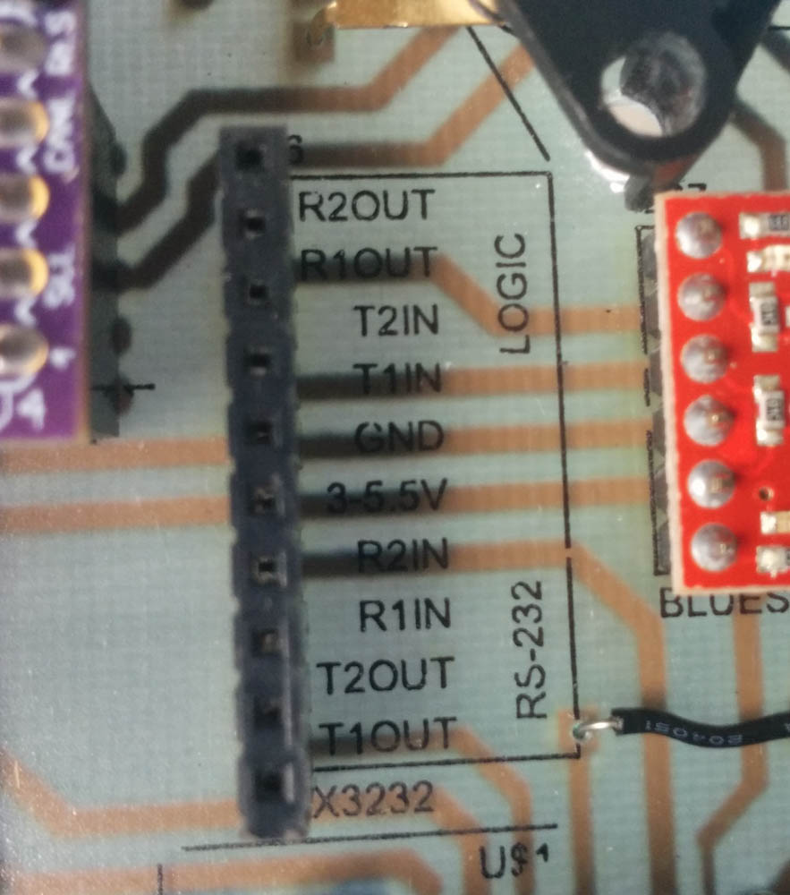
This is where the RS-232 tranceiver breakout board is plugged in. Notice something funny with the traces?
In the picture, note how there are traces going to “T1IN” and “T1OUT” (that’s the transmitter 1 input and output) and “R2IN” and “R1OUT”… Whoops. The board has 2 transmitters and 2 receivers, and apparently I had wired up the inputs and outputs to different recievers. That certainly explains why nothing was coming back.
I think I know what happened here. My custom-made EAGLE symbol for the breakout board had the inputs on one side and the outputs on the other, but I never bothered to line up the two inputs with the corresponding outputs. So when I made the connections, I must have just connected the pins that lined up, without verifying the labels.
Oh well. While annoying, it’s easy to fix.
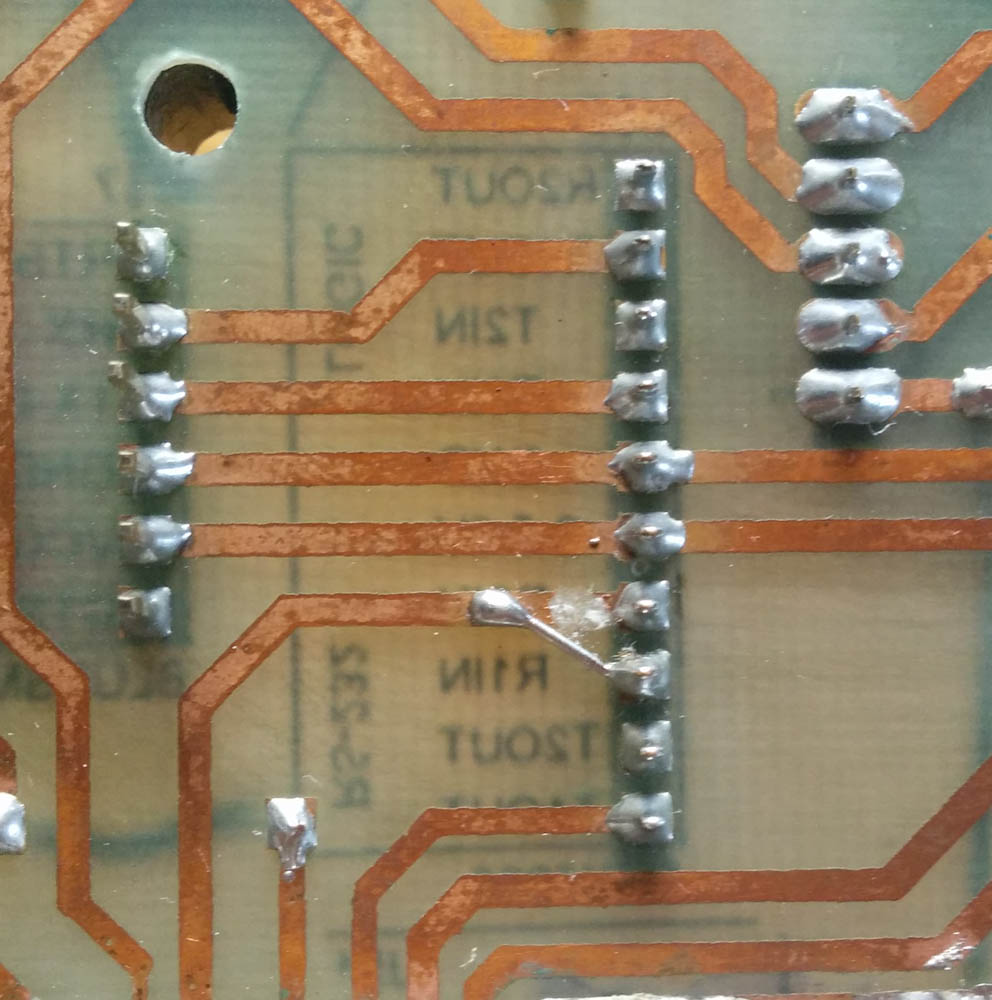
Problem solved. After this change, the communication worked perfectly.
With that, the Microsquirt connected up to the tuner software on the laptop fine, so I proceeded to wire up the remaining connections.
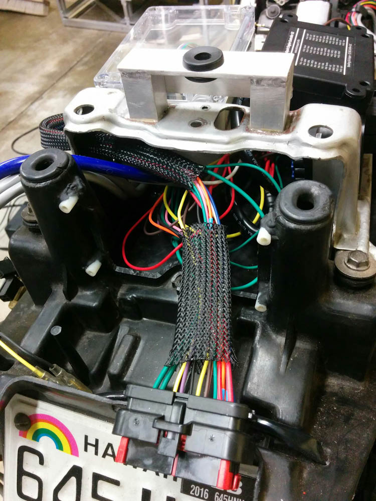
After connecting all remaining wires to the appropriate pins on the 35-pin connector, it’s getting quite crowded in that little space.
After entering the correct calibration constants for the pressure and temperature sensors, I now have sane-looking sensor readouts.
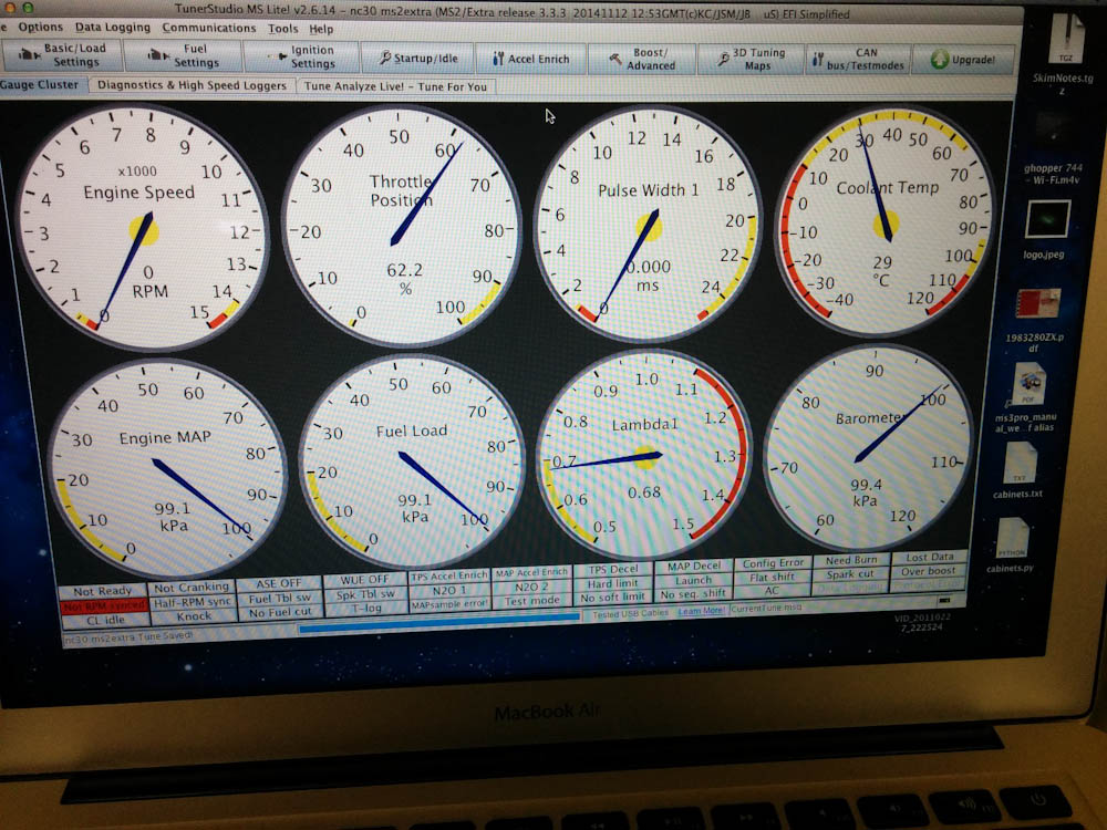
Both pressures and temperatures look reasonable.
The manifold and ambient pressure reads 99kPa (the weather station says the current pressure is 99.8kPa) and the coolant and intake (not shown) temperatures were 29C. Seems satisfactory.
I also verified that the control of the radiator fan works by telling it to turn on at 25C. This did indeed turn the fan on.
The only remaining thing to wire up is to connect the oxygen sensor wires to the wideband controllers. I didn’t want to cut those wires until I knew what things were going to look like, but now the time for that has come too.
Pingback: Microsquirting the NC30, part #7: Reading lambda | Patrik's projects
First of all, Great work! Stayed up late reading through everything. You gave me ideas for future projects. Do you have a wiring diagram? I am building a 98 rc46 with the microsquirt. Really needing to know how to wire in the rectifier. Bike was already fuel injected but I want to take advantage of better AFRs.
Hey, thanks!
I do have a wiring diagram, it started out in EAGLE but has then been scribbled and color coded after how everything was wired up. (Or do you mean the Arduino/bluetooth/CAN board shown in this post? I do have that. (I even have extras of the CAN/Arduino circuit board since OSHpark has a minimum order of 3, if you want to go that route I’ll be happy to mail you one. Although you have to mod it because it’s had a bunch of fixes done to it.)