As mentioned over the last few posts of the NC30 EFI project, I’m going to need to fabricate various little metal parts. That’s not something that I’ve had the capability of doing here. Back when I got the ShapeOko, I was hoping it was going to be able to do light aluminum work. While I managed to cut some parts out of a 1/4″ plate, it took forever and ended up with the end mill clogged with aluminum due to the low feed speed. The cuts were also not very good, the gantry setup is just too flexible to be able to do aluminum well enough to be useful.
So, over the past month or so I decided that I wanted to get something more capable. You can get super nice “benchtop” CNC mills like the Tormach PCNC 440 for something like 7 grand (ayour bench better be solid because it weighs 450lbs) plus shipping, tools, etc. That’s just a little bit more than I want to spend, though.
At the other end in price (and capability), you have the ubiquitous “Harbor Freight” Mini mill, for $650, available from 4 or 5 different suppliers that put their own nameplates on what is the same Chinese product. There exists a small cottage industry dedicated to improving, upgrading, and converting these mills to computer control. The $650 really only get you the basis for a project, where you have to add your own motors, ball screws, etc, to be able to control it. If you google on “mini mill CNC conversion”, there are literally thousands of posts and videos of people doing this. The problem is that the basic mill has a very small working area and is marred by some other basic flaws that need fixing or that limit the ultimate result.
As a step up, the people at LittleMachineShop.com have developed their own variant of the same mill, the HiTorque mill, that fixes some of the worst flaws of the basic model. For $250 more, you get a more rigid structure, larger table, and a better spindle motor. This is what I decided to get.
For the CNC conversion, the standard kit is the one from CNC Fusion, which includes ballscrews and ball nuts, bearings, motor mounts, etc. Then you also need the electronics. Since I feel more comfortable in this area I decided to assembly my own components here.
In the end, all the parts ended up somewhere around 2.5 grand, but this includes shipping and also the basic things you need to actually use the mill, like a vise, end mills, indicators, mounting hardware, etc. (If it’s 1/3 as capable as the Tormach remains to be seen…)
I didn’t take any pictures of the mill as it arrived in the crate, but there are enough pictures of it on the web anyway. The mill arrives completely covered in grease, like dripping with it, so first order of business is to clean all that off and then replace with a light coat of oil for rust protection. (I’ve had enough of my tools rust here in Hawaii that I’m super paranoid about wiping everything made out of metal down with 3-36 after use now.)
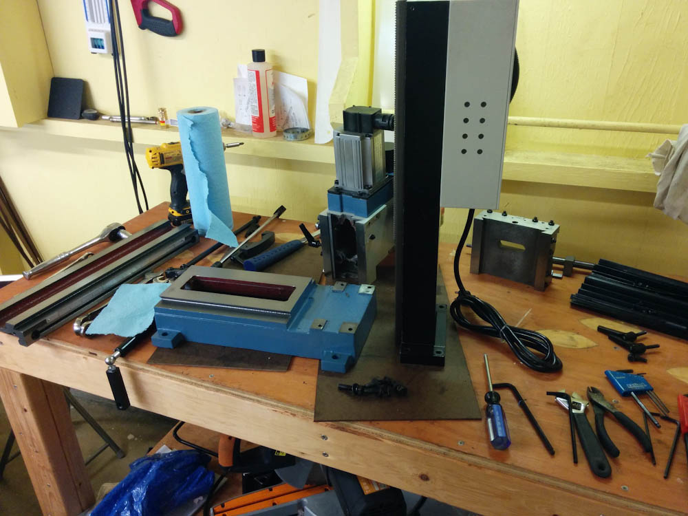
Here’s the mill fully torn down for cleaning and installation of the CNC kit.
The CNCFusion kit is mostly bolt-on (once you’ve removed the old lead screws and other stuff like hand wheels you don’t need on a CNC machine), but there are a few places where you have to make some modifications.
One thing you have to do is drill 4 holes in the top of the column for mounting the Z-axis motor mount. It seems most people do this by hand drilling, but given the need for reasonably accurate positioning I was not excited at the prospect of hand-drilling 4 5mm holes through roughly 20mm of cast iron. Since the mill was basically torn apart anyway, I removed the motor electronics box from the column so I could drill the holes in the drill press instead. This worked much better.
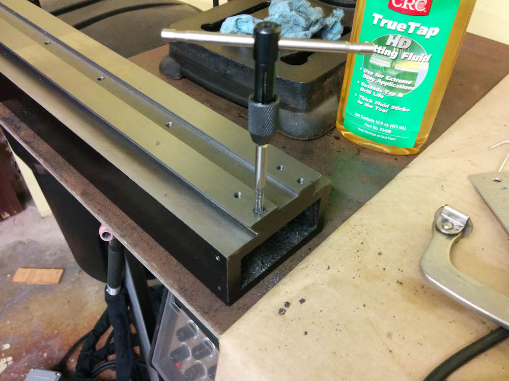
You’re required to drill 4 holes in the column. Rather than trying to hand drill these holes through the ~20mm thick cast iron, I tore the mill down to the bare column and drilled it in the drill press and tapped them with M6 threads rather than use nuts. The tap was almost not long enough, I had to go all the way down to the point where the threads end to get the holes tapped all the way through.
Another modification needed is to remove some material from the base so the end of the Y-axis ball screw will fit. (If the ball screw was made shorter, you’d lose some Y-axis range, because the ball nut assemblies are much longer than the nuts used by the leads crews.) I did this with the Dremel, and it was shaping up to be a long and tedious job until I realized I had bought this high-quality 1/8″ carbide end mill specifically for steel. Since 1/8″ shanks fit in the Dremel, I tried using it and it sure cut a lot better than the other Dremel tools! It would have gone even better if the Dremel bearings were better, because if I tried to push the bit hard I got extreme chatter. Nevertheless, it probably didn’t take more than half an hour to get enough material removed.
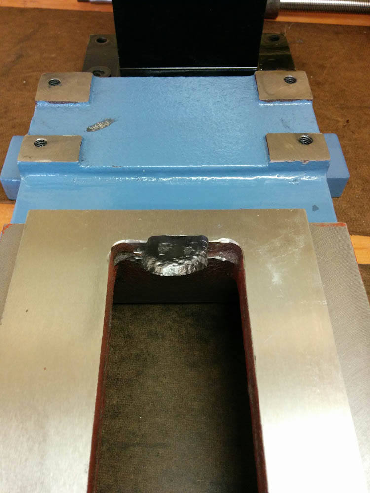
One other modification that has to be done is to grind out a small piece of the base so the Y-axis ball screw will clear it. This was going to take forever with the Dremel, until I realized the 1/8″ carbide end mill I had bought also fits in the Dremel…
With those modifications out of the way, it was down to assembly and adjustment. This largely went OK. The assembled table looks like this.
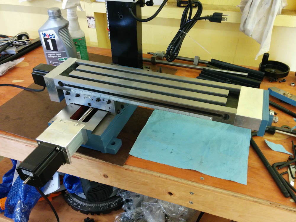
The assembled table, complete with stepper motors. The column is still not mounted.
I’ll save the electronics box for another post, but at this point I hooked up the motors and started running things back and forth to make sure everything ran smoothly. While it works, I’m having some issues with the ball screws not sitting square in the bearings. I don’t know if they are actually bent or if they’re just not seated right, but it makes it impossible to get them to roll smoothly all through the range. It appears I’m not the only one who’s had this problem, so I’m waiting for word back from CNCFusion as to whether this is a machining defect or if something can be done about it. Here’s a video showing what’s happening:
While this causes some binding of the ball screws that you can feel when turning them by hand, the stepper motors don’t seem to have a problem moving the axes. I worked my way up to some rapid moves that I recorded as well:
There are a few things that would be very good to have, like limit switches so I don’t accidentally run any of the axis into the end stops, and some sort of guard to protect the Z-axis ball screw from chips and other junk. I also need to hook up the spindle motor to the controller so it can be controlled from the G-code as well, but at this point it should be good enough to try some cuts.
Pingback: The mini mill motion controller | Patrik's projects
Pingback: Welding the intake runners – Patrik's projects