As of the last post, the bike was running with all sensors functional and it was time to make the Microsquirt finally do something useful: control the ignition. To understand the setup, we have to go into some amount of detail.
The way (most) ignition systems work is using an ignition coil, which has two windings, a primary, with few turns, and a secondary, with many. The coil is “charged” by running a current through the primary winding. When this current is suddenly interrupted, the rapid change in the magnetic field induces a very high voltage in the secondary winding, which is attached to the spark plugs.
In ye old days, the coil current was started and interrupted by mechanical “points” on a distributor, but these days it is electronically controlled with a semiconductor “switch” instead. This makes it possible to adjust the ignition timing based on all kinds of various variables that wasn’t possible (or at least very difficult) with a mechanical system.
The stock ignition system on the NC30 is electronic. There are two ignition coils, one each for the front and rear pairs. These are hooked up in what’s known as “wasted spark” mode, meaning both ends of the coil winding are connected to a spark plug, so firing the coil fires both spark plugs at the same time. This works because the NC30 has a “360-degree crank”, shown below on a picture shamelessly stolen from someone on the internet.
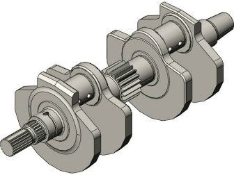
The NC30’s “360-degree crank”. The engine is like two identical V-twins, side by side.
Each crank throw is connected to one front and one rear piston, so the engine effectively is like two identical V-twin engines mounted side by side. This means that when one front cylinder is between the compression and combustion stroke, ready to fire, the other is “360 degrees” (hence the name) away in the 720-degree 4-stroke combustion cycle. This puts it between the exhaust and intake stroke, so the cylinder is empty and has no burnable fuel in it. Hence, it doesn’t matter if that spark plug fires at the same time, it is just “wasted”, hence the name. The same applies to the rear cylinders.
This design means that we can get away with only two ignition coils even though we have 4 cylinders (which is good because the Microsquirt can by default only drive 2 ignition outputs) and it also means the engine controller doesn’t have to know where in the combustion cycle the engine is, since one of the two cylinders will fire every revolution. This saves us from needing to sense the camshaft position, further simplifying the ignition setup.
The stock ignition unit senses the crankshaft position using a pair of “pulse generator” coils mounted around the crankshaft. These coils pick up the passage of “teeth” on the starter clutch wheel, sending a signal to the ignition unit. The wheel has 8 teeth, i.e., one every 45 degrees, but one of them is missing. The missing tooth makes it possible to know where in the revolution the crankshaft is. The two coils are offset by about 72 degrees, effectively giving a 16-tooth resolution. 72 is 45+27, so the signals from one coil are pretty much halfway between those from the other, effectively doubling the resolution. (As well as making it possible to tell which direction the crankshaft is going in, but that should hopefully never be necessary…)
This ignition unit also contains the electronic “switches” used to turn the ignition coils on and off, so removing it means something else has to fulfill that function. The Microsquirt itself doesn’t have the ability to switch the high coil current, so this must be done by an external component, in my case a Bosch ignition module that I got on ebay. First order of business was to mount that somewhere.
The rectifier will be moved from the stock location on the left (where it’s really too large to fit) to this new bracket made out of 1/8″ aluminum.
As I started looking for places to put the ignition module, I decided I should just go ahead and move the regulator as well. Back when I did the regulator upgrade, I shoehorned this in where the old one had been mounted, but it really didn’t fit well there. Every time I’ve taken the fairing off, I’ve had to bend it to go around the new, larger, rectifier, so since I was going to have to make some mounting bracket anyway, why not move the rectifier to a better place, too?
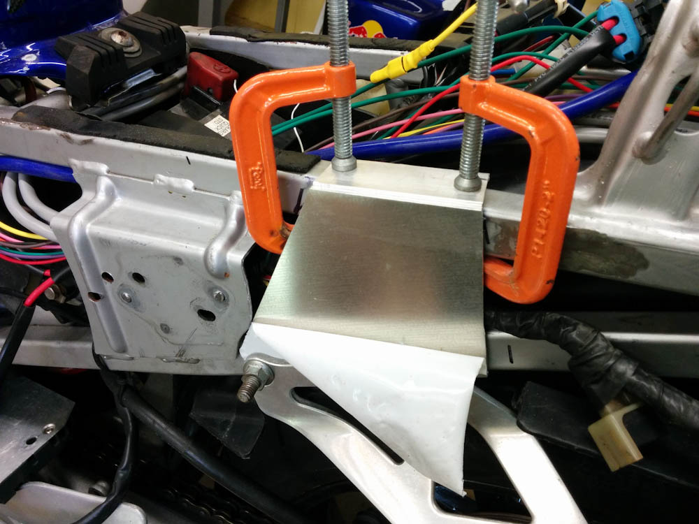
Moving backwards from the old location (on the left in the picture above), the fairing is much wider and there’s a lot more space, so I decided to make a sturdy aluminum bracket and attach it to the bolts that hold the muffler hanger. By welding a piece on top, I could then attach it to the top part of the subframe, too, and it would be really sturdy.
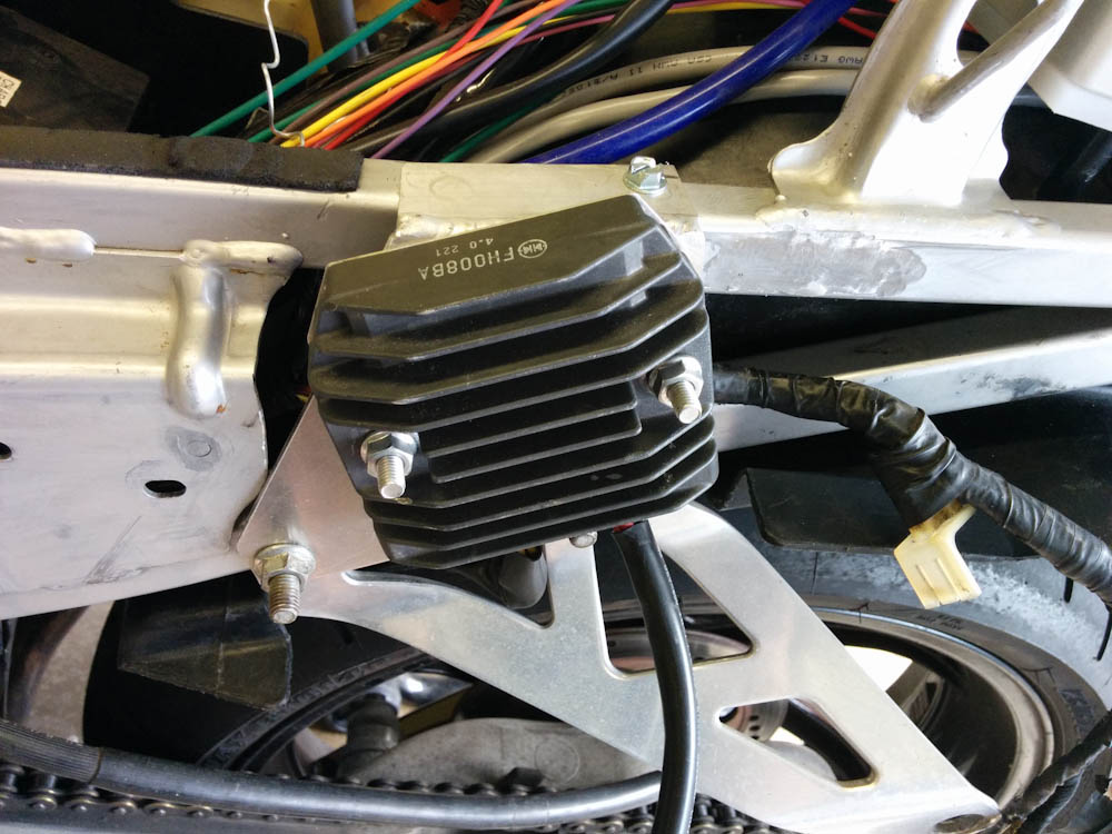
The new mounting for the rectifier worked out really well. Until, that is, I tried to put the fairing back on…
The fabrication of this piece went well, until I had mounted the rectifier on it and tried to put the fairing back on and had it hit the top of the rectifier! I’m not sure how this happened, I trial fit the fairing on numerous times. The only thing I can imagine is that it actually had hung up on something and wasn’t seated right, so I incorrectly thought I had more room than I really had.
The real problem with this is that the rectifier can’t move down, the bolts holding the exhaust hanger are in the way. I tried grinding off the top of the rectifier heatsink (it doesn’t really get warm at all) which helped but not nearly enough. After being upset with myself for a while I realized that the way to get it to fit was to tilt it forward. It looks kind of bad, but a least it fits.
With that problem solved, I could now mount the ignition module, which is much smaller than the rectifier, where the rectifier used to be. It needs a flat surface for thermal conduction, so I had to make sure the remains of the rectifier studs were all ground down, but then it fit without a hitch.
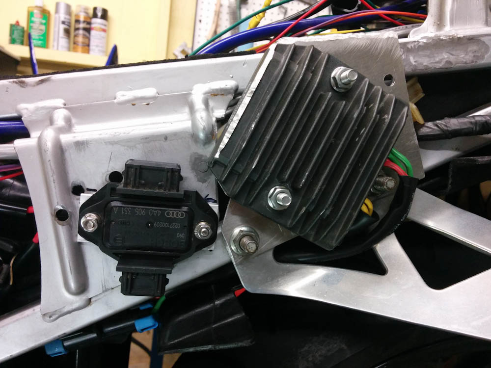
The new ignition module mounted where the rectifier used to be, and the rectifier in the rotated position where it clears the fairing. It doesn’t look very good, but it’s not visible from the outside.
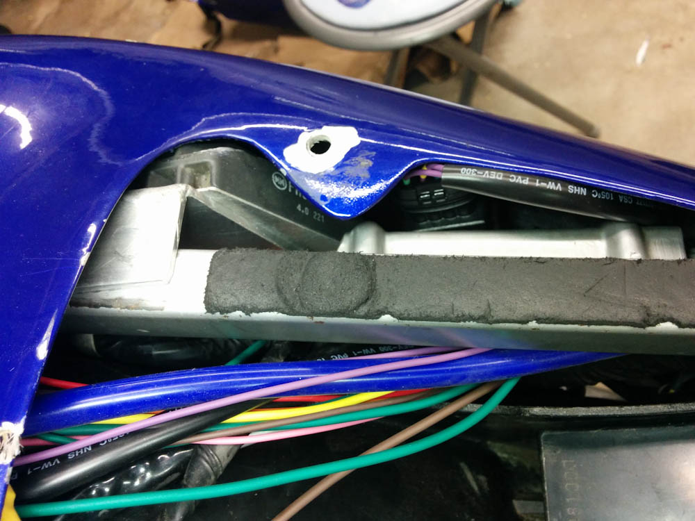
This picture illustrates how little space there is between the top of the fairing and the rectifier. The ignition module, by comparison, has tons of space.
With the hardware mounted, all that remained was to wire it up. Two wires go to the Microsquirt ignition outputs, and then I hooked the outputs up to the same connector the stock ignition unit was connected to. This way it’s easy to swap back and forth between the old unit and the Microsquirt, which I bet will be useful during the test phase.
With this wiring completed, I fired up the laptop and put the Microsquirt into “spark test mode”, where you can fire each of the ignition coils with different parameters, and it worked perfectly.
Next order of business is to hook it up to the pulse coils on the crankshaft.
Pingback: Microsquirting the NC30, part #11: Crank trigger | Patrik's projects