After getting the spark hardware hooked up, it was time to get the Microsquirt to know about crankshaft motion. As I mentioned in the last post, the motor has two “pulse generator” coils offset from each other. My hope was that the signal from these coils could be hooked up as-is, since this is a sort-of standard sensor type and the “8 teeth with one missing” pattern is readily settable with the Microsquirt. The one problem with 8 teeth might be that it forces the ECU to extrapolate up to 45 degrees into the future, so if crankshaft speed changes during the rotation, the ignition timing might be a bit inaccurate. For this reason, it is recommended to use at least 12-16 teeth on a high-revving engine like a motorcycle. (For a car, 60 teeth is the standard.)
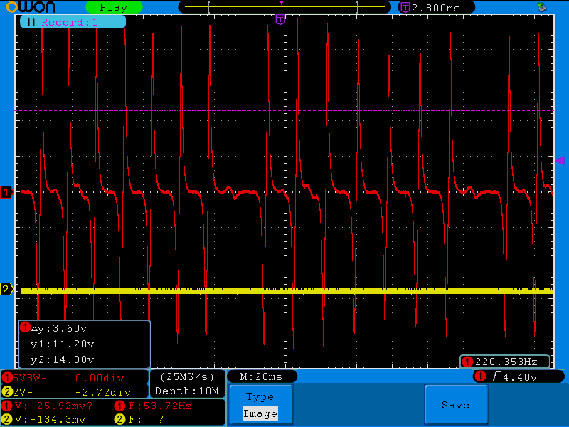
This is the output from one of the pulse coils. There are 7 peaks, and then one missing where the eighth one should have been.
As can be seen in the oscilloscope picture above, the signal is about +-20V with very sharp transitions going low to high. These sharp transitions happen when the tooth is passing by the coil, while the flat transition going the other way is when the teeth are midway. (It’s important to get the polarity right here, if the Microsquirt is looking for a transition going low, it’ll pick up the very indistinct midway-between points and nothing will work right.)
It was pretty quick to hook one of the coils up to the Microsquirt inputs and set up the trigger type, and when I tried cranking the engine (with no gas in it) I was immediately rewarded with a fairly stable rpm reading. The software will alert you to any “sync loss” which happens if it can’t detect the missing tooth or if the signals are very uneven, and this looked perfect. The tooth log below looked exactly as it should.
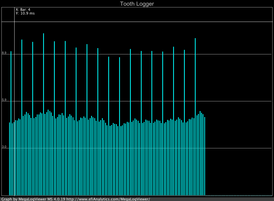
This shows the “Tooth log” output from the Microsquirt. Each bar is a tooth signal, and the height is proportional to the time between it and the previous tooth. The “8-1” tooth pattern shows up as 6 bars and then one with twice the height. The slight variation in bar height is because the crankshaft speed slows down on compression strokes and speeds up when combustion happens. (This is actually with the engine idling, not cranking.)
The next step is to physically verify that the crankshaft is where you think it is using a timing light. Setting ignition angle to 0 (at TDC), the timing light should show cylinder #1 at TDC, and it did. Since this engine has uneven firing order, I thought it prudent to also verify that the spark for cylinder #2 went off when it was at TDC, which it also did. Time to see if it would start. For the moment, I set timing to a constant 18 degrees BTDC which is the factory-specified idle timing.
After putting the tank back on and cranking a little to fill the carbs with gas, it started uneventfully and idled quite nicely. Verifying timing again, now with the engine running, still showed cylinder #1 dead on and cylinder #2 maybe a degree off from the timing mark. This was almost going too well…
The first setback happened when I gave it some gas. It basically refused to rev much above idle, making a sound like a rev limiter was in effect. The log also showed numerous sync loss events and now the tooth log looked like this:
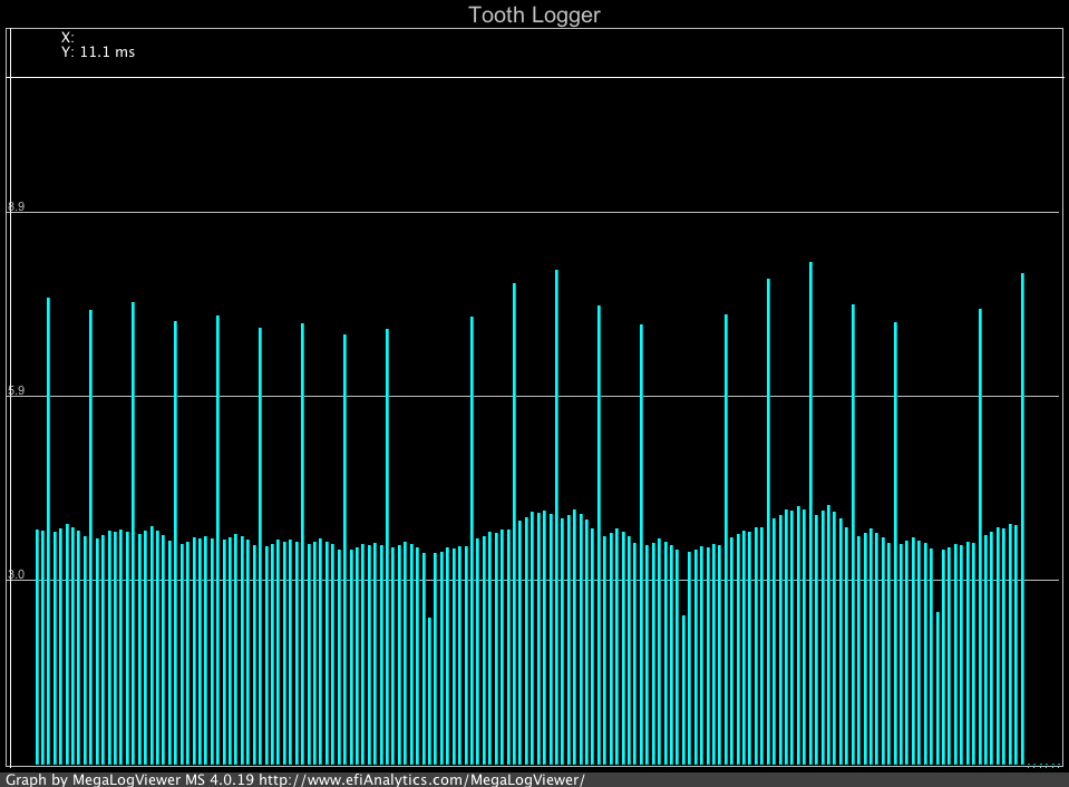
This is the tooth log trying to give it some gas. The nice long-bar sync pattern is replaced with a shorter bar instead, which is what you’d expect if it was picking up the little peak associated with the missing tooth.
Turns out this is not an entirely uncommon situation. The issue is that when the engine speed increases, the voltage output from the coils increase to the point that the tiny little peak associated with the missing tooth in the scope trace above gets picked up as a real tooth. The solution suggested is to put a resistor across the coil to reduce its output voltage, and sure enough, with a 1k resistor the problem went away and I was rewarded with a clean rev without sync loss. It wouldn’t go past 10k RPM, but since the timing was fixed at 18 degrees that’s not unexpected.
Before I could go on a test ride, I would need a more realistic ignition timing curve at higher RPM. The factory manual specifies that timing start to advance from 18 degrees at 1800RPM and reaches max advance of 37 degrees at 12000RPM. The simplest thing to do was to just assume a linear advance between those two points. (I still want to measure the timing curve with the stock ignition unit, but that’s a bit complicated so I haven’t gotten around to it yet.)
With that curve set, I took it for a test ride. It runs pretty much the same, except that I got a very noticeable knock at full throttle around 7-8k RPM! This is a bit surprising. One possibility is that the ignition curve actually advances more slowly through this region, such that my timing is too far advanced. The other possibility is that my timing is off at high RPM (and perhaps high loads. It seems likely the crankshaft speed is most uneven at full throttle, when the combustion events have more torque.)
I don’t think the timing should be that off, because the position of the teeth are such that “tooth #1” (the one after the missing one) is detected 126 degrees BTDC. Since there is a tooth every 45 degrees, that means tooth #3 passes at 34 degrees. For advances less than this, the Microsquirt only have to extrapolate from 34 degrees down to whatever the advance is, so it seems that should be reasonably accurate. For very high RPM, when the advance becomes greater than 34 degrees, though, it has to go almost the full 45 degrees from the earlier tooth, so that might be more of an issue. Since the two cylinders are 90 degrees apart, this reasoning holds for both cylinder pairs.
I guess the first thing to do is to actually measure the timing at higher RPM than idle. More on that next.
Patrik,
When I was getting ready to set up the ignition control on my GSF400 I looked around on the internet to research the ignition curves of other similar engines.
Here’s some of what I found: Yamaha FZR400 – idles at 10 degrees BTDC, ramps up to 38 degrees BTDC by 3,500 rpm. Kawasaki ZXR400 – idles at 12.5 degrees advance, ramps up to 45 degrees BTDC by 6,000 rpm, Kawasaki EX250 – idles at 10 degrees BTDC, ramps up to 42 degrees BTDC by 4,500 rpm. Suzuki GSX400F – idles at 15 degrees BTDC, ramps up to 35 degrees BTDC by 3,500 rpm.
I couldn’t find a similar reference for my own GSF400, Suzuki only gives an idle specification of 15 degrees BTDC.
In the mystifying Japanese-language copy of the ’88-’89 GSX-R400 manual I see 15 degrees BTDC at idle and a reference showing the advance varying from 15 degrees to 45 degrees, but no accompanying rpm. The ’85 GSX-R400 manual shows 15 degrees BTDC at 1,650 rpm at idle and 35 degrees BTDC at and above 3,500 rpm.
Yeah, if you look at the next post where I measured the ignition curve, it ramps up much faster than “linear between 2k-12k.” It’s not even monotonic…
Pingback: Microsquirting the NC30, part #12: Timing measurement | Patrik's projects
Pingback: Microsquirting the NC30, part #12: Timing measurement – Patrik's projects