Finally, it was time to go for a test ride. You can view and log data over Bluetooth with a phone using the MSdroid Android app. Going out for a ride, everything seemed good until the RPM gauge spiked to 10k and then back down. Uh oh — this is what the Atmega does when it boots, so this was an indication that it had rebooted “in flight”. That’s not supposed to happen. A few moments later, the RPM gauge started going totally nuts, bouncing between 10k and max, down to zero, jumping around randomly, and then dying.
This is the most frustrating part about programming an Arduino — you can’t just run it in the debugger and see what’s happening. I commented out various parts of the code to see if I could isolate what was causing it, but it seemed semi-random. By going over the code with a fine-toothed comb, sure enough, I found one instance of a forgotten “&”, hence using the value of a variable, rather than its address, as a pointer. I also found another place with flawed logic that could lead to writing to random places in memory. But even after fixing this, the problems remained. I didn’t get the random behavior of the RPM gauge anymore, but it would still reboot.
Looking at the logs, it was interesting to note that sometimes the Bluetooth connection to the Microsquirt was interrupted at the same time the . That’s a totally separate circuit, the only common part between the bluetooth modem and the microcontroller is … the power supply!
This shouldn’t be a big surprise, actually, automotive power is notoriously noisy, and this is an area that I don’t know that much about. If the power circuitry didn’t properly insulate the microcontroller from various transients, that could easily be causing the problems. To test this theory, I went for a spin with the alternator unplugged. Sure enough, the problem went away.
Ok, time to rip up the electronics box again. I’m getting quite skilled at it, though.
The conversion from 12V to 5V is done by a tiny MIC5205 voltage regulator on the circuit board OshPark made for me. It’s specced for 150mA, and the Atmega, CAN-bus controller, transceiver and the Bluetooth modem all use no more than 70mA. Sounds fine, right? Not quite. The maximum current is one limit, but it turns out that most often, the max current output is limited by the maximum power dissipation.
Linear voltage regulators change an input voltage to a lower output voltage by essentially converting the excess power to heat. This means that the regulator will dissipate a power equal to the current passing through it times the voltage drop, V_in-V_out. The limiting factor is the maximum temperature of the silicon junction, so how much power can be passed through it depends on how efficiently heat can be transported away. (This is why it helps to put heat sinks on stuff…)
Well, it turns out that using the thermal resistance quoted by the datasheet, when supplying 70mA the regulator will overheat when the output-input voltage difference is maybe 3-4V (depending on the ambient temperature). That would be an input voltage of 8-9V, when in reality it is being fed 12V with the engine off and up to 15V when running! There’s no way it can handle that much power, and when it overheats, it will go into thermal shutdown. No wonder I’ve been having problems!
So, I pulled the circuit board out and thought about what to do. The obvious solution is to add a pre-regulator that will take the 12-15V down to <8V that the MIC5205 can handle. I happen to have a box of LM317 regulators. Those are big (TO-220 case) and can handle a lot more power. The only hitch is that they are adjustable and require some extra components, so it wasn’t so easy to add it onto the existing circuit, but it worked out. Here’s what I ended up with:
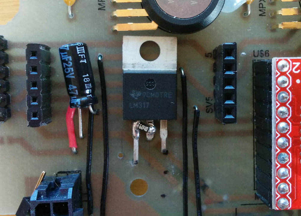
This is the newly added LM317 voltage regulator, sitting between the headers that the circuit board with the CAN controller fits into. It’s almost half the size of that entire board… The resistor soldered across the pins in part of the voltage divider that sets the output voltage. Also added was the 47uF capacitor immediately to the left.
As you can see, the LM317 ended up fitting nicely under the CAN controller circuit board. If you look hard, you can see the 12V supply trace on the back side has been cut, and routed through the input and output pins on the LM317 (on the right and center, respectively.)
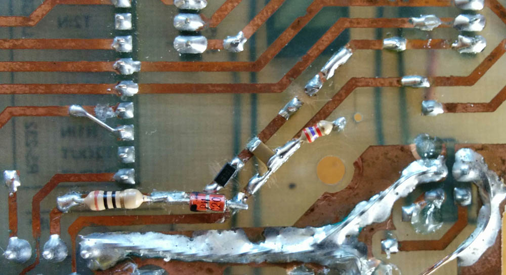
Here’s where it gets ugly. A bunch of components were added to the back side of the board.
To set the output voltage, you need two resistors. The first is soldered between the output and adjustment pins right next to the case. The second is on the back of the board and goes to ground (the 2.7k resistor on the right in the picture above.) The tan square is the 4.7uF capacitor for the LM317 regulator input.
While I was adding stuff, I decided to add a diode (the small black component) that prevents this circuit from being pulled down if there is a transient low-voltage event. The glass component is a 20V zener diode that protects against transient overvoltages (and reverse voltages) by shunting those to ground, and the 10 Ohm resistor will limit the current that needs to be shunted in those cases. It also forms an RC low-pass filter with the capacitor, but its time constant is 50us so it will only help against high-frequency noise.
On the LM317 output, I added a bigger 47uF capacitor, which in principle will be able to supply the 70mA current for half a millisecond.
While it’s certainly not improving the increasingly ghetto-looking circuit board, it actually worked pretty OK to add the components across the traces. Now I’m happy I made those traces as wide as I did!
Testing the new circuit, the MIC5205 seems a lot happier. When I ran it on 12V before, you’d burn your finger touching it. Now it’s not noticeably hot, and the LM317 was warm-ish to the touch, even with 15V input. Seems pretty promising.
After mounting all the circuit boards into the box again (did I mention I’m getting good at it?), I went for another test drive.
Flawless!

This is an example of what the data look like. The axes are manifold pressure and lambda, with RPM being the color scale. As suspected, the bike runs really rich, typically around lambda 0.8, and it even saturates the wideband sensor at 0.69 lambda a significant part of the time at full throttle.
Over 20 minutes, there was not a single hickup. Clearly that meant problem solved, so I immediately went for a ride up the Saddle Road all the way up to the Mauna Kea visitor station at 9200 feet. (I wanted to get data on how what the air/fuel ratios with the carburetors were all the way up there before starting to change things.) Above is an excerpt of the logged data.
As expected, the bike is running rich. Very rich. The plot above is near sea level and shows lambda (air/fuel ratio in relation to the ideal 14.7) against manifold pressure, essentially throttle opening. It appears to run at about lambda 0.8 for partial throttle, and the full-throttle lambda goes all the way down to 0.69 which is as rich as the SLC lambda controller reports!
As you might expect, this got worse at altitude. (Carburetors meter fuel against air volume, not mass, so as air density decreases, they run richer and richer.) Going up the final 2000ft, the lambdas were often pegged at the 0.69 limit. The bike runs really poorly at that altitude, and I guess that’s not a surprise.
For reference, maximum power for a gasoline engine occurs at about a lambda of 0.86. At full throttle, you might need to go a bit richer than that, maybe to 0.82, to prevent the engine from knocking. But running at 0.7 would not only make much worse power, it would also make the exhaust really sooty (check) and smelly from vastly increased hydrocarbon emissions (check). Not to mention waste gas. The two cylinder pairs also run at noticeably different lambdas. I think there is plenty of room for improvement here! 😉
Now that I know the sensors are working, the next step is to pull out the stock ignition module and get the Microsquirt to handle the ignition.
Patrik,
Near the end of this section you mention the fact that the two banks of cylinders in your Honda V-4 (front pair vs. rear pair) run different Lambdas. This is an interesting situation.
In the past I’ve heard and read mentions of this condition and in every instance it was wholly attributed to unequal heating of the fore and aft cylinder banks. Is this really the only contributing factor or are there other additional additives that you know of? For example, are there subtle front cylinder head/rear cylinder head differences in the intake airflow routing (from the bike’s airbox through to the carbs) that contribute to this situation? Or differences (fore vs. aft) in the effects of the NC30’s airbox resonance? It seems that Honda engineers either couldn’t overcome the difference(s) that caused this situation or they simply chose, for one reason or another (like production costs/unit price-point), not to undertake whatever design steps that might have been obvious/necessary, deciding instead to compensate by changing the carb settings.
Greg
I don’t know what causes this. If you look at http://blog.familjenjonsson.org/blog/2015/08/23/microsquirting-the-nc30-part-5-more-wiring/, there is a picture of the intake runners. The front and back ones are parallel and close together, and they both make the same 45-degree joggle to align with the carburators (only in the opposite direction). The air enters the airbox from the front (upper right in the picture) so I guess it’s possible that the fact that the rear-cylinder intakes are closer to the rear wall of the airbox could mean the airflow could be different. If you read people’s experiences on 400greybike, the NC30 appears to be notoriously unforgiving of modifications to the intake system. There is a rubber flap blocking air coming through the upper radiator from flowing directly onto the carbs that apparently is essential for the bike running correctly. There’s also a snorkel fitted to the airbox opening (which my bike is missing) that may affect airflow.
Short answer is, there are many variables that could possibly affect the front and rear cylinders differently and it seems likely the design is a compromise. It will be interesting to see if this difference persists with the fuel injection or if it’s something inherent to the carburetors.
Incidentally, the intake seems very strangely designed to me. There is no clear way for the bike to draw clean air into the airbox. That area is pretty much sealed in under the tank, so air can’t get there without coming up from between the engine and the frame, which should mean the air has been pretty warmed up already. I think this is confirmed by the datalog, which showed an intake temp of 31C even at the top altitude where the outside temp probably wasn’t more than 12C or so. Certainly nothing close to a “cold air intake”…
Thanks for the reply,
It seems that the items/issues you touched on in your reply are (perhaps to varying degrees but nonetheless) about keeping carburetors happy. Keeping carbs “happy” often ends up being a leading issue/headache in the maintenance of older motorcycles and often feels like equal parts science and voodoo.
I think you may have a ready source of information available for exploring/diagnosing how much of the NC30 design was directed toward simply making the carbs happy enough to work reliably, how many design compromises they were responsible for generating, because Honda stuck with the V-4 well past the carb era. A good number of their motorcycles used the same V-4 engine architecture but with fuel injection instead of carbs. I’d imagine that a careful study of these OEM Honda setups might be a revelation to you, both from the perspective of discovering specifically what was (or wasn’t) done on your NC30 just to accommodate the needs of the carbs and, perhaps more importantly, for input/direction for your project by way of examples of what Honda felt were the best engineering practices for configuring a V-4 engine with fuel injection.
Really enjoying your project.
That’s an interesting idea. The NC46 is the earliest FI VFR800, and that engine belongs to “the other” Honda V4 lineage with 180-degree cranks, so it’s not the same design. However, that shouldn’t matter much for the intake/TB design, so maybe it would be useful to see what they’ve done in that area.
Have you looked at the throttle body off the Kawasaki EX300? It’s a nice little pair of Keihin 32mm intakes, perfect size for a high-revving 100cc cylinder. If the bore-spacing happened to be the same as on your NC30 maybe you could fabricate a set of brackets (like the VFR800 has).
Just a thought.
Pingback: Microsquirting the NC30, part #10: Spark hardware | Patrik's projects
I looked at a bunch of throttle bodies. The EX300 certainly would be in the right size, but the bore-spacing is way too small. Because the NC30 has the cam gears between the cylinders, the bores are quite wide apart, and those throttle bodies don’t look very amenable to being separated…