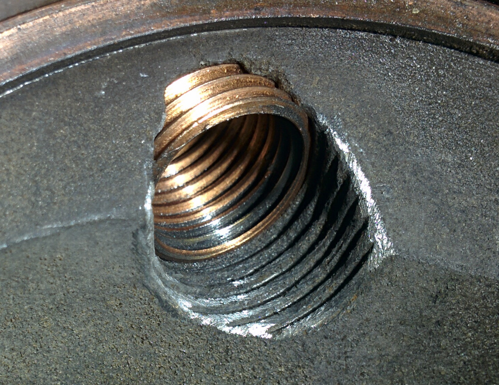
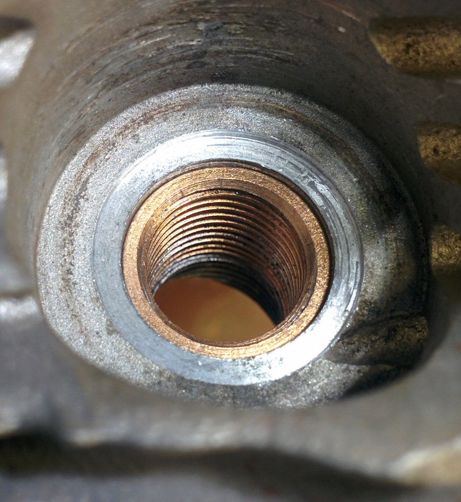
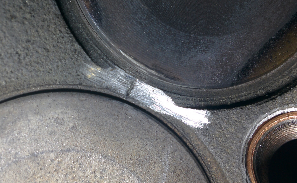
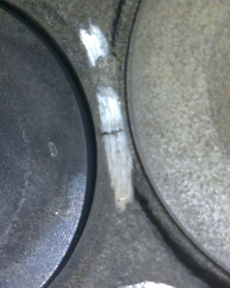
Well, we dodged the head bullet. The people at Sonex said the small cracks between the valve seats in the cylinder heads are typical of the VW heads and unless the valve seats are compromised they are nothing to worry about.
Relieved to hear that, I put the heads back on the engine and fired it up again and it ran perfectly. In fact, the static RPM at full throttle even went up a little, which I guess is the performance lost to leaky sparkplugs before. We now have a static RPM, with the recommended Sensenich 54×44 propeller, of 3240-3260.
I did some further AeroCarb tuning, trying the richer needles. The Aerocarb needles are numbered #2, #2.5, #3 etc. It had #2 in it, and the full rich fuel flow was about 25l/h. The problem was that when adjusting the needle, the adjustment seemed to affect the idle much more than full throttle, such that the idle would get so lean it wouldn’t run without making any noticeable change to the full throttle fuel flow.
Apparently the manufacturing tolerances on the needles, especially on the ones from a decade ago like the ones we have in our carb, are kind of loose and there’s a lot of variation. Some Aerovee owners reported better results with the #2.5 needle, so I gave that one a shot. This increased the maximum fuel flow to about 32l/h, and brought the exhaust gas temperatures down quite a bit compared to at a fuel flow of 25l/h. It also appeared to bring the cylinder head temperatures down such that it’s now possible to run full throttle for almost a minute (with the cowling on, no less), so this may be the final solution to the overheating problem. Most people seem to think that this is way too rich for an Aerovee, but there were no signs that the engine was running excessively rich. In particular, RPM was down only tens of RPM compared to the best I’ve seen. This will require a bit more experimenting but I think it’s good enough to go for a test flight and see how it works.
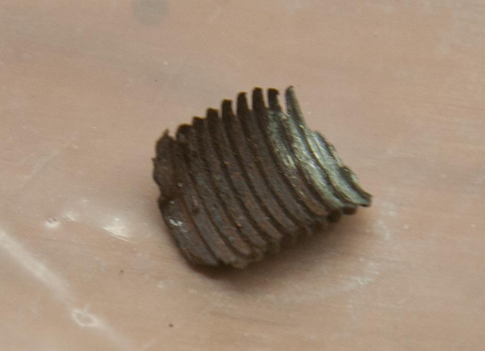
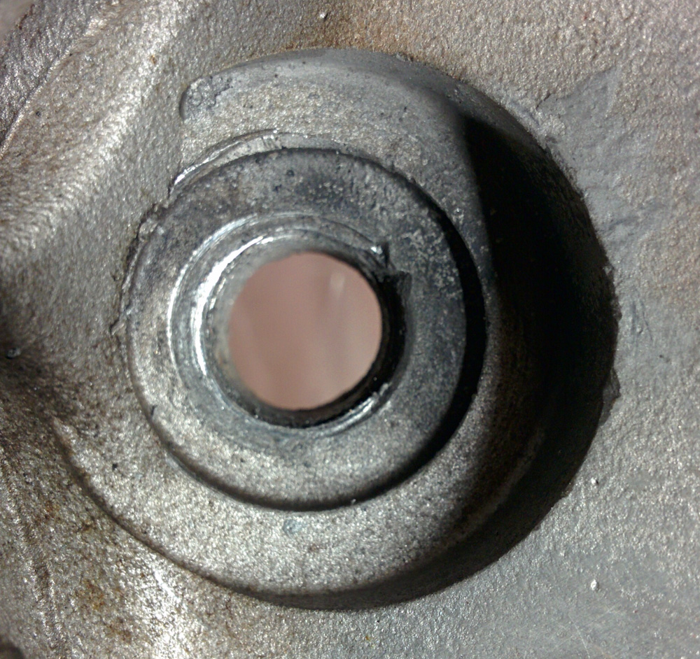
But that won’t be for a while, because something else has come up. I noted back this summer that there’s a very noticeable axial play in the crankshaft when turning the prop back and forth a little. I thought this seemed funny but unfortunately I didn’t check the spec on how much play there should be until I came across an article that described how excessive axial play usually comes from the crankshaft thrust bearing having spun and worn down the case so the crankshaft can move back and forth excessively.
I went down and measured our play to be 0.020-0.025″ (about 0.5mm) and the spec is 0.006″, so it is 3-4x as much as it should be. This may also be incorrect assembly, as this play is set by adding shims when assembling the engine. Unfortunately the crankshaft banging back and forth by more than it should also can damage the thrust bearing.
I consulted with my Sonex tech support who pretty much said it needs to be fixed and while you can just re-shim it, you don’t know if there’s internal damage unless you take the engine apart and look at the bearings. So that’s what we decided to do.
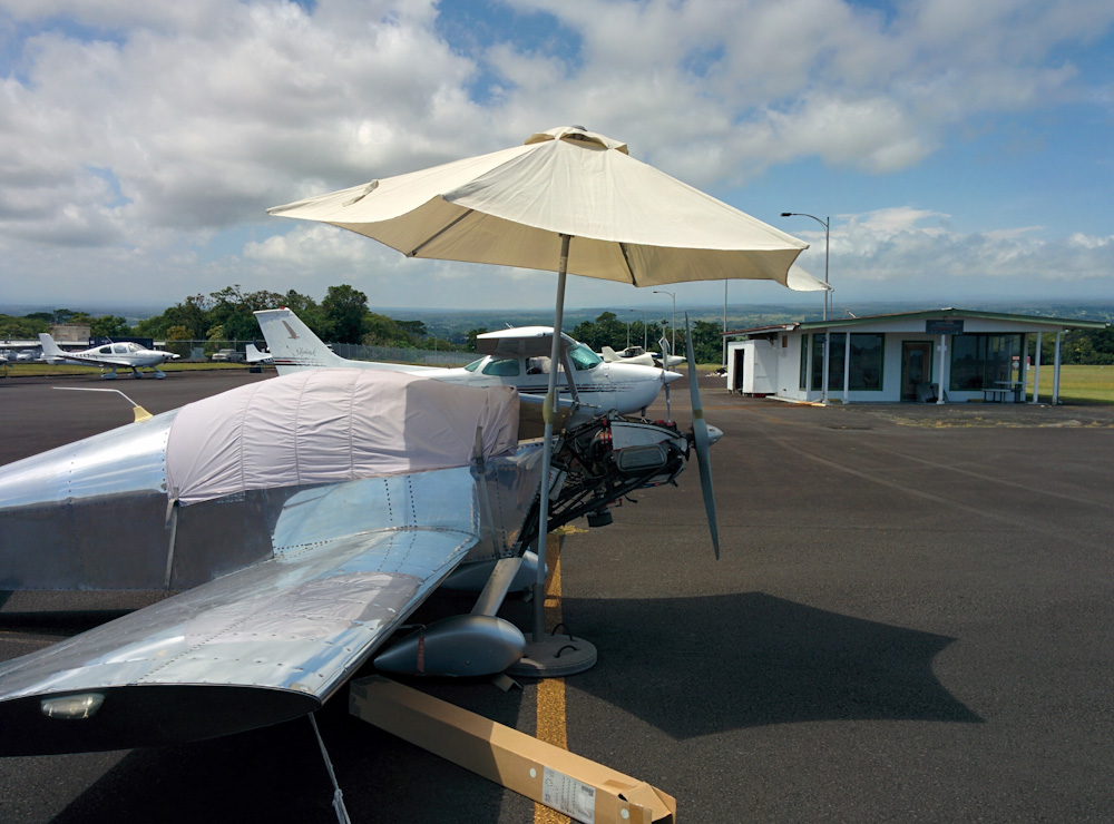
Needless to say this is disappointing, but it will also be interesting to get a better understanding of how the engine looks and also give us a chance to make sure there is no internal corrosion on the cam and lifters. Corrosion is a significant problem in engines that aren’t run for long periods of time and since the Sonex has been sitting outside in Hilo with quite little use for five years or so it’ll be good to take a look.
Look forward to a new post with lots of engine guts…