With the 3D-printing trials and tribulations overcome, I pulled the left half of the plenum off the printer.
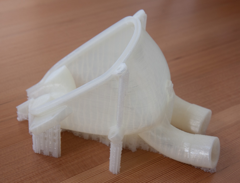
This is the left half of the plenum as it came off the printer. It looks good and is plenty strong, but the shiny parts indicate that the outermost perimeters aren’t always fused properly. (I think the very shiny reflection essentially comes from total internal reflection against the inside of the round plastic string extruded by the nozzle. When they are fully fused, the part becomes much more transparent.
The two halves fit well together, so I proceeded to melt in the brass M5 thread inserts for the mounting bracket and the screws that hold the halves together. The plastic parts were now ready to be assembled.
The welding of the left-hand intake, on the other hand, did not go so smoothly. The first runner went on fine, but when I attempted to weld the second one (where access to the area between the two pipes becomes difficult) I managed to blow a hole in the aluminum tubing. After a few attempts it was clear that filling the hole was not going to happen. After fuming about this failure for a bit I decided to just run with it and fill the hole and the area between the two intake runners with high-temperature JB Weld. This is good for 450+F and if the intake gets that hot something has really gone wrong…
Although it’s not used in a structural application, I’m not sure I trust JB Weld to hold up in flight. The first order of business, however, is to figure out if this setup is even any good, and it’s certainly going to be fine for that. If we decide that we’re not comfortable flying with a JB Welded intake we can ponder redesigns that will make it easier to weld.
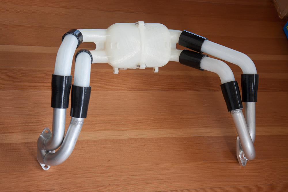
Here’s how the whole thing is going to look, intake flanges, runners, and plenum.
Before we go and put this shebang on the airplane, I thought it would be fun to recap how the design evolved.
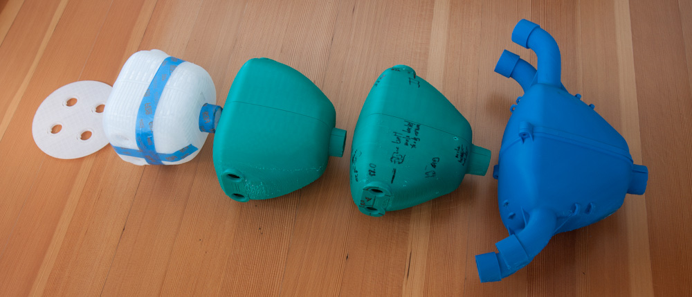
The progression of the plenum design, starting with the cylinder with four runners exiting upward on the left through the increasingly non-cylindrical shape we’ve ended up with on the right.
From the initial design, the plenum went from a cylinder to a much more tapered shape, and it also increased in volume substantially. The first drafts, before I realized how the plenum could be enlargened without interference with the engine mounts, had a volume that was significantly smaller than the engine displacement of 2180 cc, I think somewhere around 1500 cc. The final shape is about 2700 cc, minus the volume taken up by the internal bellmouths, so it probably comes out slightly larger than the engine displacement. This is good, the rule of thumb for plenum volume is that you want no less than the engine displacement.
Today I spent most of the day down at the airport (being baked on the black apron in the tropical Sun) putting all the parts on the engine. Apart from having to remove a mm or so of material from some spots on the rear cylinder head cooling fins where the front intake runners come down, everything fit well.
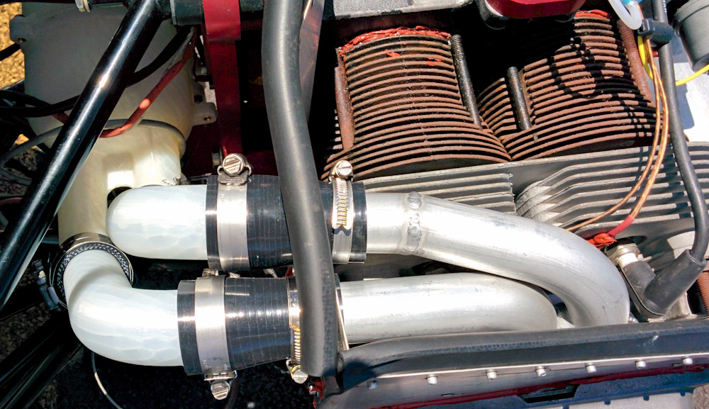
The new intake mounted on the engine for real.
There are a lot of clamps. We’ve gone from 6 hose clamps on the old intake to 18 on this one. This is not awesome, since it means many more opportunities for leaks, but there’s no way around that with individual runners. The only alternative would be to make either the plenum or the intake with very long, curved runners, which would in practice be impossible to fit.
The new setup moves the AeroCarb back by about an inch, which makes the fuel line too long. It’s fine for testing, but eventually I’ll need to shorten it. It also required some adjustments to the throttle and mixture cables, but they can be moved around more easily than the fuel line.
The first test run should be coming up rapidly, hopefully this weekend. Stay tuned!
Pingback: Testing the new intake – Patrik's projects