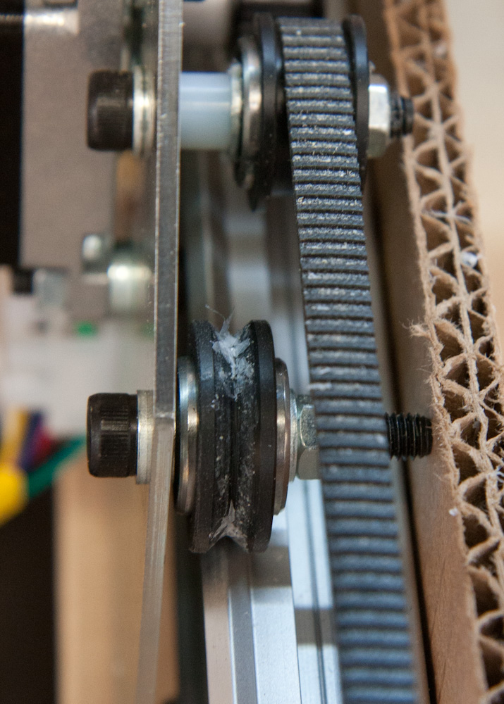
I got a big chunk of 1/4″ 6061 aluminum plate and tried to mill it, with pretty depressing results. The setup just was nowhere near rigid enough to handle it. The force on the bit would cause enough flexure to pull the bit to the side or cause it to jam into the material. A complete failure. The problem was the axial loads on the wheels running on the rails. Most of them have a bit of play in the axial direction which means it’s possible to rotate the setup a little bit around the rail. This translates to several mm of play at the bit.
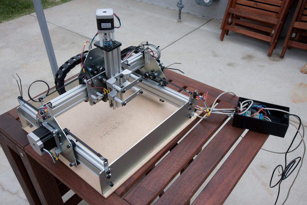
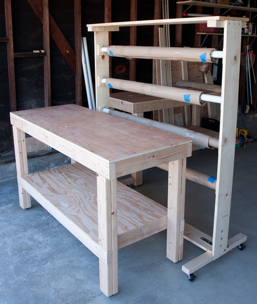
The obvious solution is to not rely on axial loads. The wheels are fine for radial loads since you can adjust the preload against the rail in that direction. This means we need to run two rails for each axis. After ordering a bunch of rails, aluminum profiles, etc, and taking the opportunity to lengthen the X-axis rails to 1m, it now looks like this:
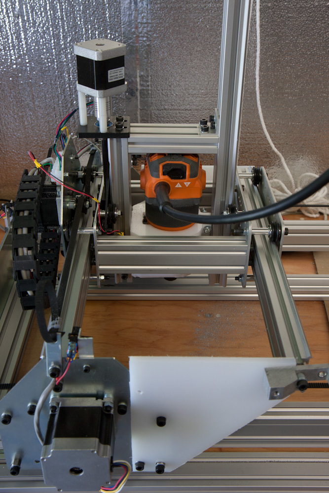
This is the new setup, with double rails in all axes. The plastic plates holding the second Y-axis rail are temporary until I can make new side plates out of aluminum.
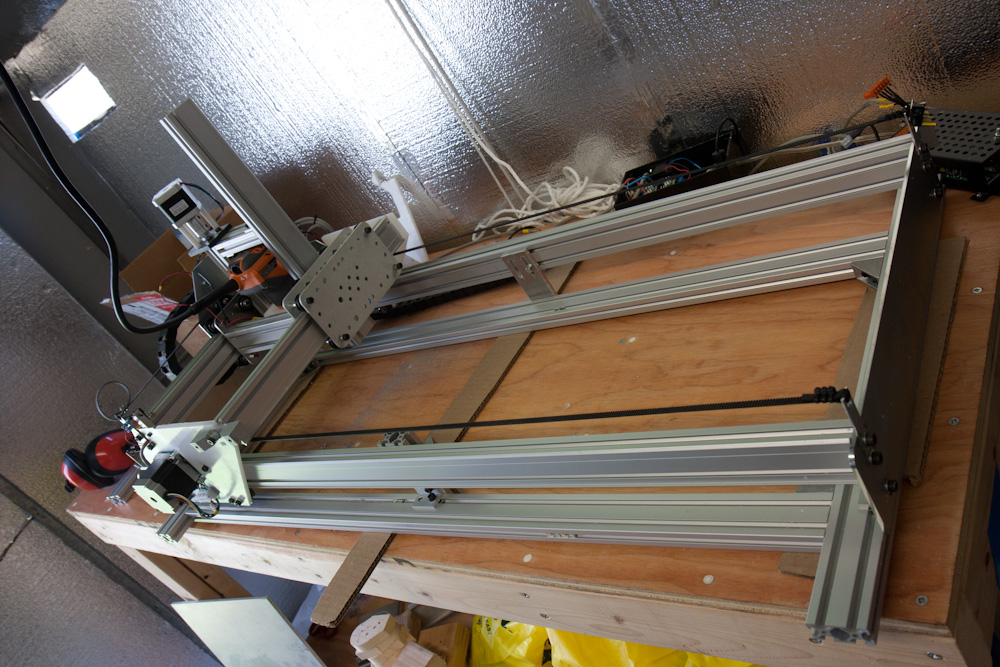
The new 1m Y-axis rails. This gives much more usable area.
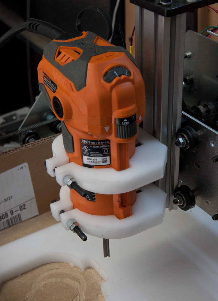
The Z-axis uses the spindle mounts, which I designed to give a 100mm spacing if you use two of them in opposite directions. Along with a 100mm aluminum extrusion they make a frame holding the Z-axis rails. The wheels for the extra Z-axis rail are attached to an extra mounting plate in the same way as the original one. This plate is mounted on two longer aluminum extrusions.
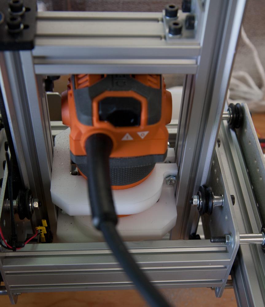
The Z axes uses a 100mm aluminum profile and the Delrin spindle mounts to get the proper separation.
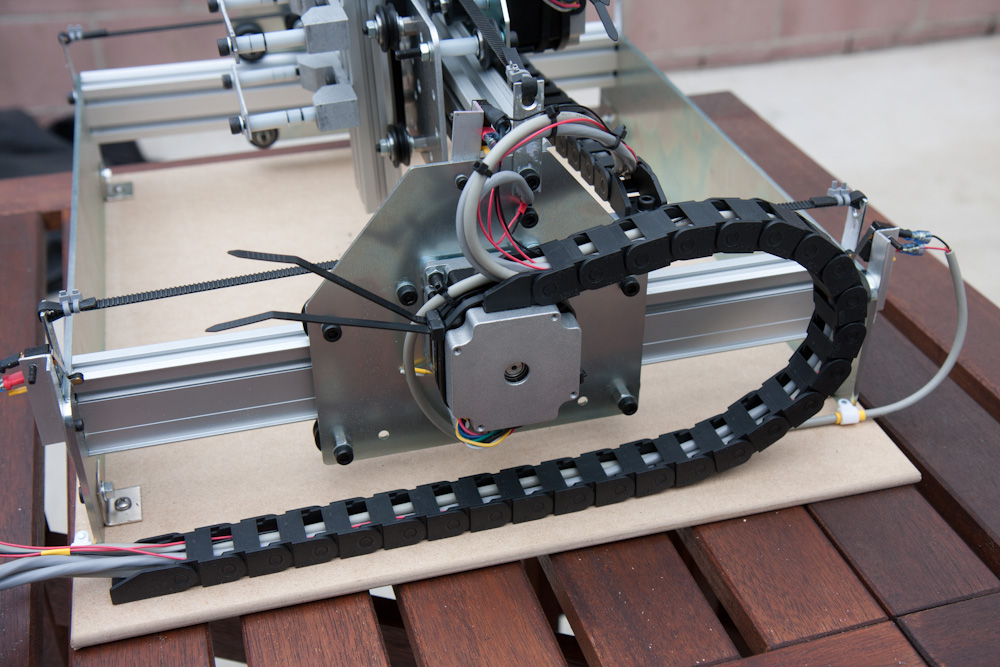
The extra Y-axis rail then needs to be held to the gantry motor plates somehow. My plan is to cut new motor plates out of aluminum, but for that to work I needed some stopgap solution so that I can actually get to a point where I can cut aluminum…. So I cut a pair of plates out of 1/8″ UHMW. They are flexible in the sideways direction, but that doesn’t really matter. In the direction that matters, holding the extra rail in the up/down direction, they are plenty stiff.
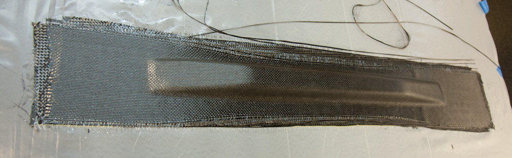
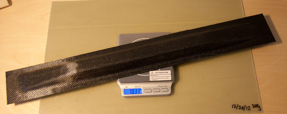
With this setup in place, I tried cutting aluminum again. It certainly worked a lot better than before: this stiffening bracket for the long rails is not perfect but perfectly usable:
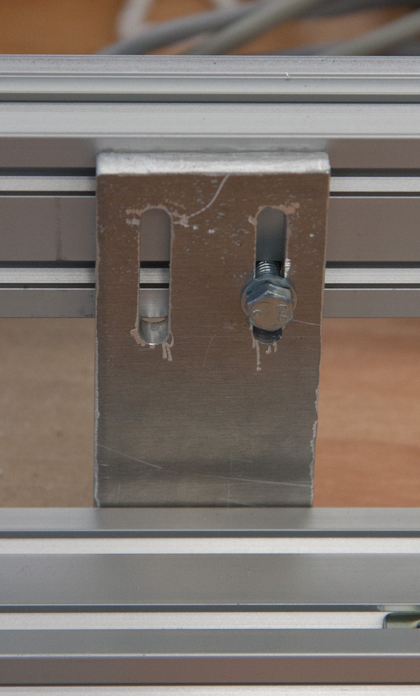
This bracket that stiffens the long Makerslide rails was cut with the ShapeOko. It needed some beautification but came out ok.
This was done with 100mm/min speed, 0.25mm cuts, and a 1/8″ HSS end mill, while spraying ethanol as lubricant from a paintbrush. However, by the end of the job, the end mill was clogged with aluminum…
After reading some stuff about cutting aluminum, it seems this is not uncommon. The problem is that you need to run the bit faster. Running too slow means the bit is rubbing against the material and heating it up, rather than cutting big chips which take heat away with them. The aluminum melts locally and ends up in the bit, and end of story.
I didn’t conduct an exhaustive test of how fast I can run, so I guess the next step is to see if how much I can increase the cutting speed. Higher speed means higher forces on the end mill, so flexure may become a problem again. I guess we’ll see what happens.