Since we moved here, I’ve constantly been annoyed whenever I’ve tried to find tools or other specific things because nothing was organized. Some things were in the basement, some things in the garage, some things in unopened moving boxes, and it was impossible to find anything. I’ve probably spent more time looking for tools than I have using them.
Another problem was the complete lack of organization for things like electronics components or even just screws and bolts. The electronics stuff have been kept in the boxes they arrived in from Mouser, so whenever I needed something I had to rifle through 50 plastic bags of surface mount components.
I thus embarked on a mission to solve the storage problem. I was inspired by a post about SparkFun’s workshop organization, where they linked to a video of Adam Savage’s workshop. Check out his storage system!
He has a rack from a system called Sortimo that uses cases with clear lids containing modular boxes. The boxes come in different sizes and can be rearranged to suit your purpose, and with the lid locked, the contents do not come out. It’s pretty cool. Unfortunately it’s also expensive. Like $100 per drawer expensive, and they’re almost impossible to find in the U.S. A little out of my range.
However, I realized that this is the goal: Everything should be easily retrievable directly from marked boxes, without rifling through things and without having to somehow pull out something from a stack. With that in mind, I searched around on various websites dedicated to hobbyist, garage setups, machinists, whatever, and finally came upon the Harbor Freight equivalent of the Sortimo system. The reviews said that they were good “for being HF”… the cases aren’t nearly as sturdy as the Sortimo, you can’t buy loose inserts, and they don’t really lock the contents securely in place when they’re closed. But they are also $9 as opposed to $90. I decided to get a bunch. Surprisingly, HF shipping to Hawaii is actually reasonable, if you buy a bunch of them.
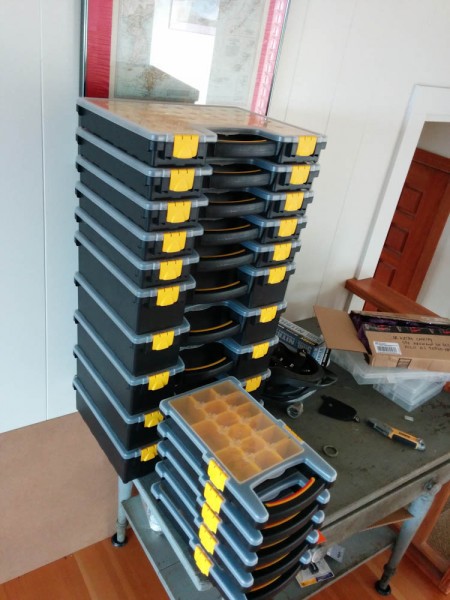
This is the set of HF storage cases I got. They are actually quite nice. The price ranges from $4 for the half-width ones to $13 for the double-height ones.
The next problem was how to organize them. They are advertised as “stackable”, but here’s where the HF quality comes in: they really aren’t. The features that are supposed to lock into each other aren’t matched up correctly. But in any case, if you stack things they are hard to get to. I wanted something like the Sortimo rack. So I decided to build one.
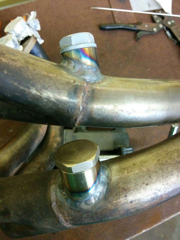
After having welded up the table, I wanted to try my hand at welding Aluminum. It’s supposed to be tricky, but what better way to get motivated to learn than to actually make something out of it?
I designed a rack made out of square tubing, with the “shelves” consisting of angles on each side of the rack, sized so the cases would slide in on the angles. Surprisingly, I realized that you can order metal from Amazon (what used to be called Amazon Supply, now I think rebranded as Amazon Business) with free Prime shipping! Compared to the local steel yard, the prices were about comparable, but Amazon’s selection vastly outstripped them (and by ordering online I didn’t have to fit 10-foot lengths of aluminum tubing in the Prius.)
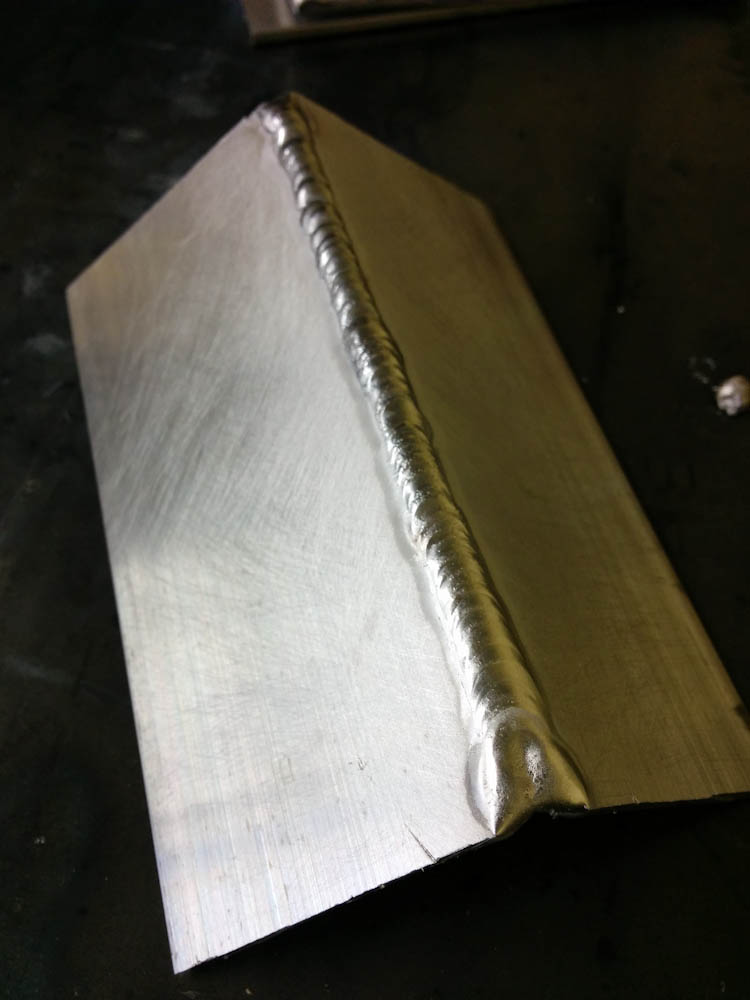
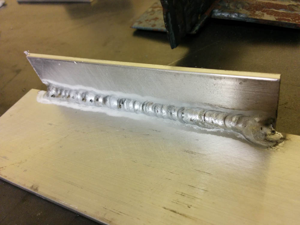
But first, I got some practice pieces.

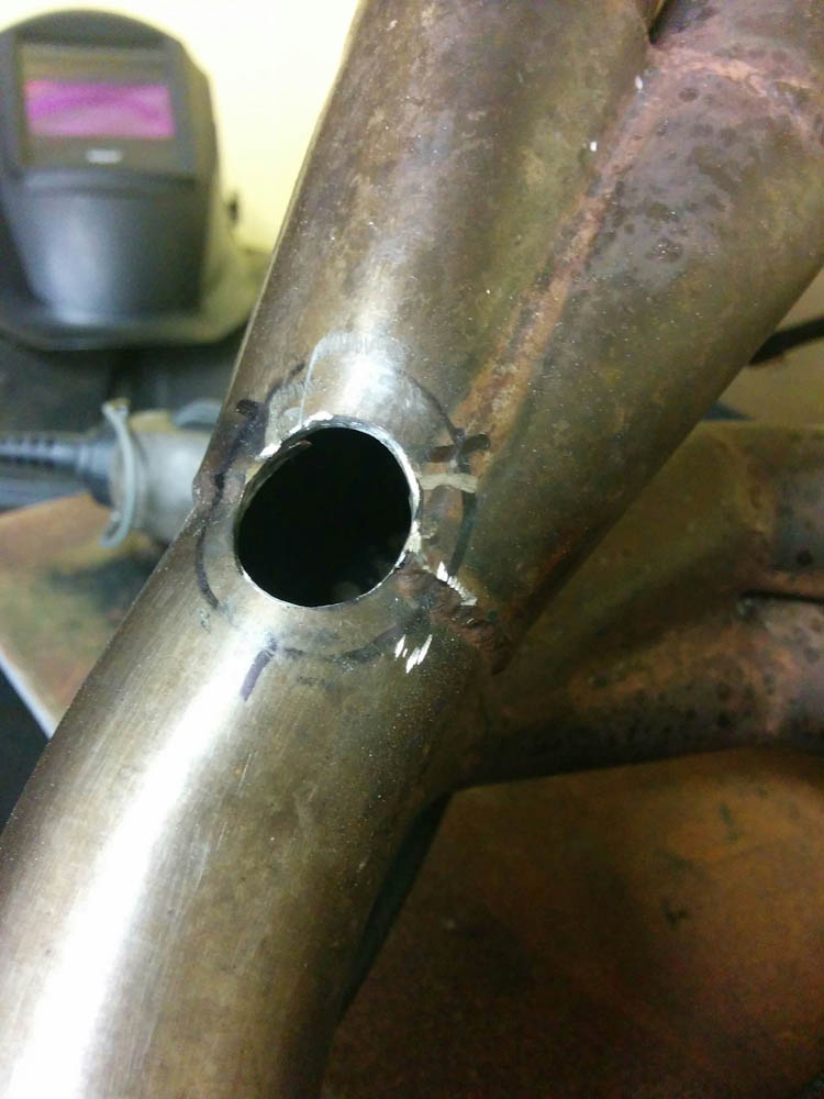
An outside corner weld.

An inside corner.
Aluminum definitely is a bit trickier than steel, because its high thermal conductivity means that heat spreads much more effectively. You need higher current, but the biggest difference is that if you apply too much heat, the entire piece can melt like a piece of ice. It definitely takes some getting used to.
After a few days of practice, the pieces didn’t look too bad, so I decided to get started.
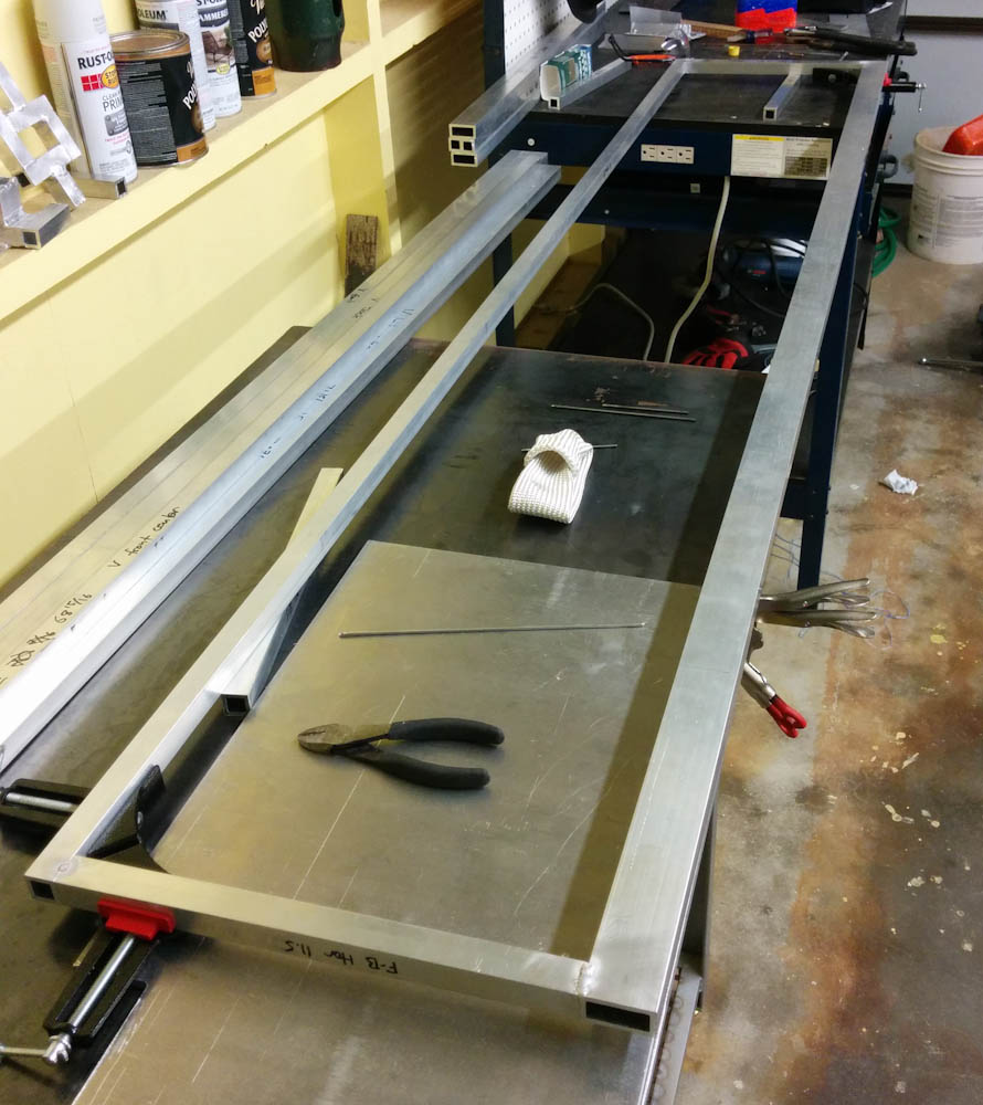
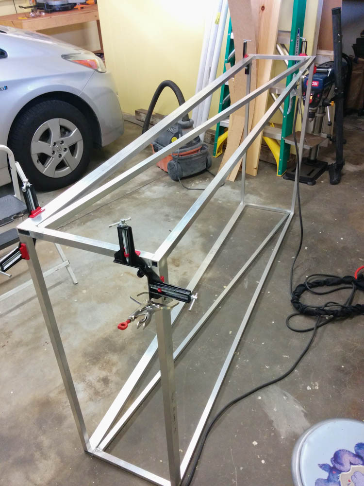
The first step was to assemble three sides to the frame (one on each side and one in the middle, since it was to be a double-wide rack.)
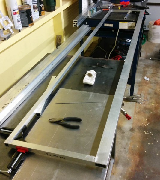
The Evolution saw made this much easier, since I could get very nice, straight cuts. With the rectangular frame assembled, it was time to add the diagonal braces that would make them rigid.
The diagonal braces were cut at an angle on the ends so they aligned with the end pieces.
These of course had to be cut at an angle so the ends would align with the end pieces. To make the welding as easy as possible, the joint really has to be well matched. Furthermore, the rectangular frame is 1/8″ material, but the diagonal braces are only 1/16″. I angled them so they should, to the greatest extent possible, be loaded in tension when the whole thing is assembled, so I figured I didn’t need them to be as thick. But welding thin material to thick is more tricky, since it’s easy to overheat the thin piece and melt it, and this gets worse if the pieces don’t line up properly. The first one wasn’t great (you can see a bit of a mismatch where I cut out material to account for the welds in the inside corners of the frame) but it worked out ok.

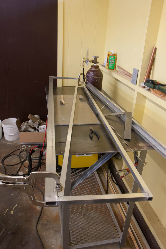
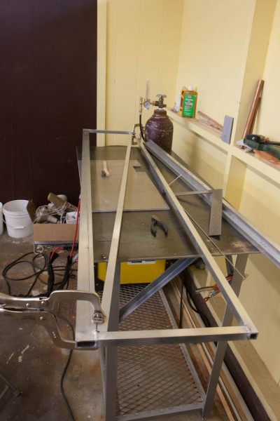
The side frames were then assembled to each other.
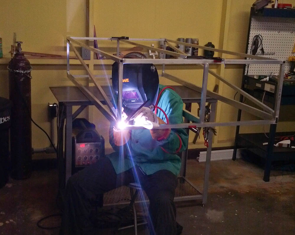
The next step was to connect the side frames with the horizontal crossmembers at the top and bottom. The sides are asymmetric, the back has 0.75″ square tubing, while the front has 1.5×0.75″ rectangular tubing. Since you can’t fit a cross brace across the front, I made the front crossmember stiffer. Of course, as you assemble more and more of the pieces, access gets harder. Here’s an action shot of me sitting inside the frame to get access to the inside corners.

Getting access becomes harder the more pieces you add… This isn’t so bad, but the cross braces across the back aren’t there yet.
This was pretty slow going, because I didn’t want to take any risks of heating the material up too much and having it warp. Aluminum has much higher thermal expansion coefficient than steel, and it also has a lower elastic modulus. This means aluminum will warp easier than steel when welded. I tried to take a lot of care to always weld symmetrically on opposite sides of the structure so any warping would cancel out. It was pretty successful, the structure on the whole is very true.
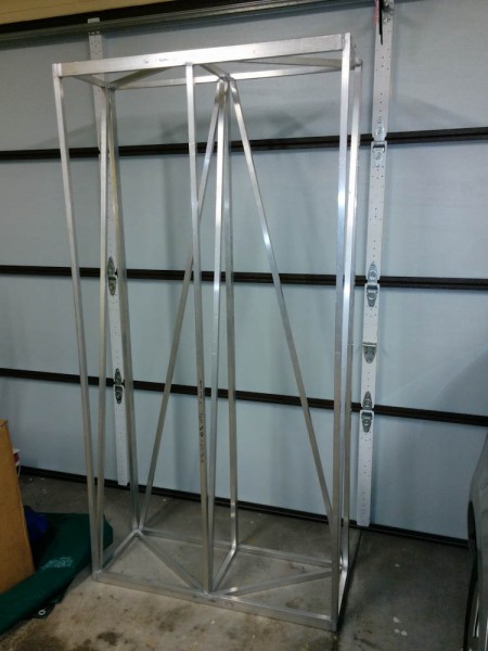
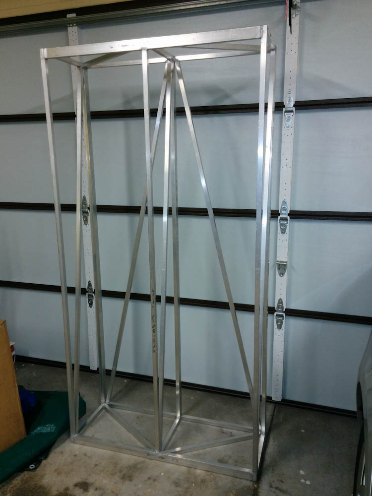
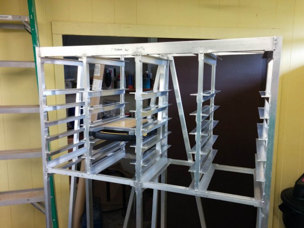
Here, the basic frame is done. What remains is to further divide the upper part into 4 sections for the half-width cases, and then weld in the shelves.
At this point I figured I was “basically done”. All that remained was to add a divider to the upper part for fitting the small half-width cases and add the shelves. This photo was taken on New Year’s Day…
Things took a bit longer than expected. The first issue was that I had never really calculated what length of angles I would need for all the shelves. As you can tell, this is a fairly large structure. It will hold 28 half-width, 16 full-width, and 12 double-height boxes. That makes a lot of angles.
The other issue was that to make sure I didn’t warp the thing I would weld one row on one side, wait for it to cool, flip the whole thing over, wait until it cooled, weld the other side, and then wait again. That, in combination with having to cut, clean, and de-burr 108 lengths of angle, meant that it ended up taking 4 months to finish the thing…
Here the top part has been divided into 4 sections and most of the shelves have been added.
But finally, the other day I added the last shelf, and apart from needing some adjustable feet so it doesn’t rock on the garage floor, the storage rack is now operational. Here it is, in all its glory, with most of the HF storage cases I bought.
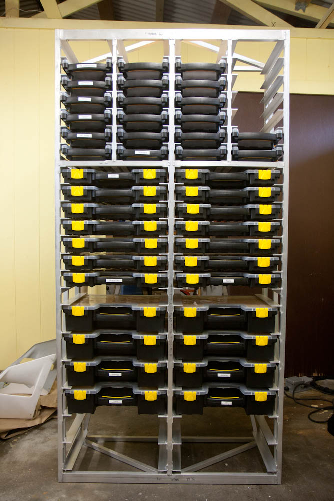
Finally, it is completed! Now I just need to actually organize stuff.
Most of the storage boxes are still empty here. It’s going to be a bit of work figuring out what should go where, but now nothing’s holding me back.
I’ve started to clean up the electronics situation. As an example, here’s the case containing Micro-Fit 3.0 connectors:

This case contains my set of Micro-Fit 3.0 connectors.
Yes, I also bought a label maker. This is going to be good!
However, I can’t really say this is a cost-effective approach. While the HF boxes were cheap, Aluminum isn’t. Argon for welding the aluminum isn’t either, and by now I’ve gone through a lot of it. I could probably buy like a hundred more of those small boxes for the money I spent on Al & Ar. But that wasn’t the point — it was an educational project. And I sure have welded a lot of Aluminum by now. Whether I’ve gotten much better… that’s more debatable. But I’m pretty sure the rack won’t come apart.