With the fusebox mostly wired up, it was time to deal with the other wires. While I’m trying to “repurpose” wires in the stock harness when possible, that mostly helps when connecting up existing things like the lights. For the new sensors, I needed to pull new wires.
First step was to add an intake air temperature sensor. Fuel injection systems need this to calculate air density and hence mass airflow into the engine. I used a small NTC thermistor I got from Mouser and drilled a small hole in the airbox for the wires.
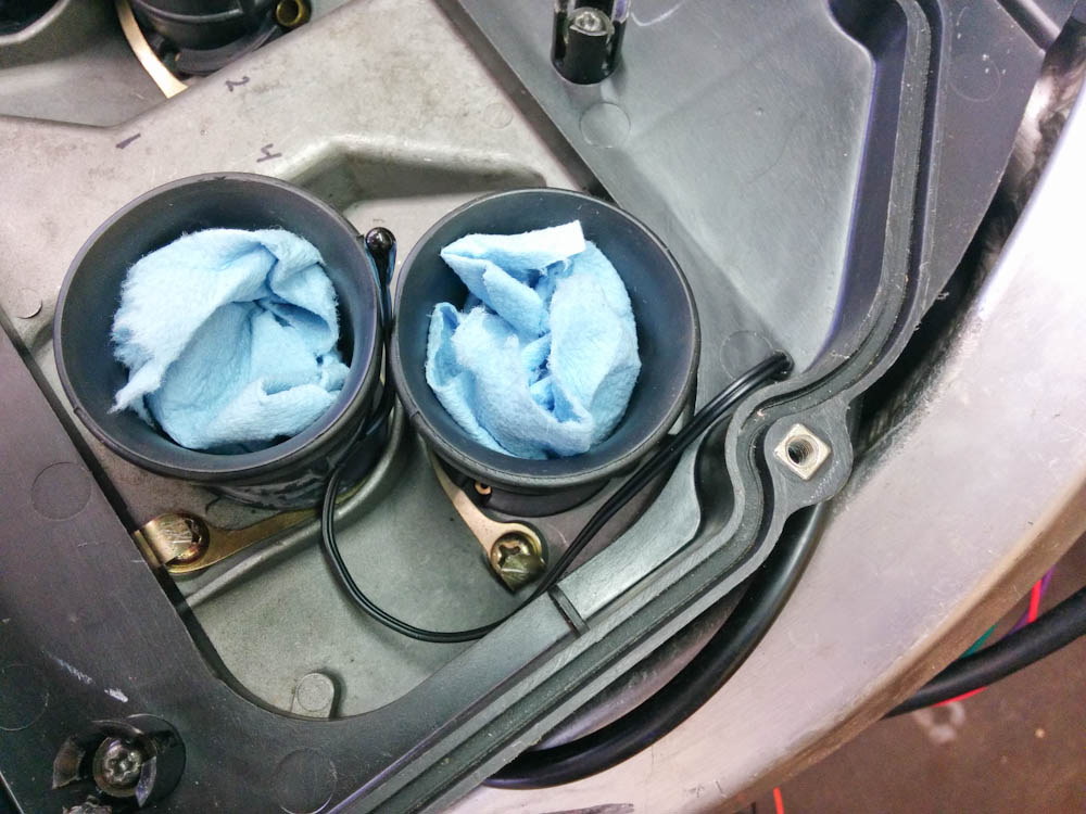
For now, the intake air temperature sensor was “mounted” by squeezing it between the velocity stacks. It weighs practically nothing, so it may even stay there. The wires exit through a small hole that was “sealed” with heat shrink tubing on both sides.
To close up the hole for the wires, I added two layers of heatshrink tubing on each side. It’s certainly not air tight, but there won’t be a lot of air going through. Since this all needs to change when the carburetors are removed anyway, I’m not too worried about making this permanent now.
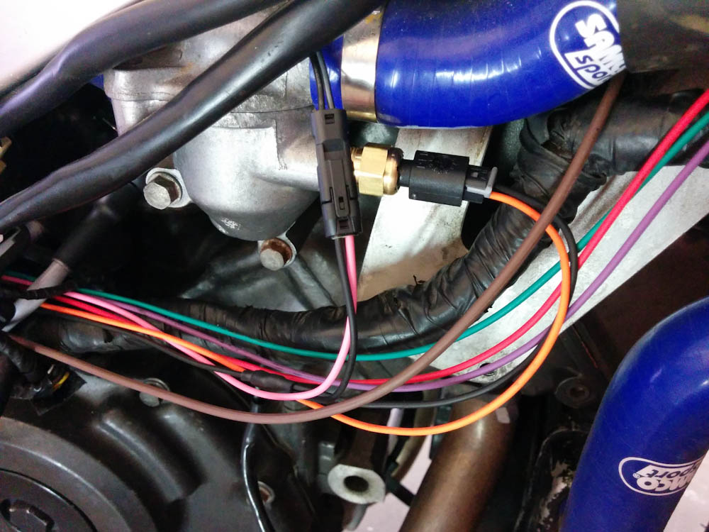
The new wires for the harness. The tiny connector in front of the thermostat is for the intake air temp sensor, Behind it is the new 2-wire coolant temp sensor. Three wires continue up to the temp gauge. The thicker, brown wire is for the radiator fan.
Rather than worry about making a new harness now, I decided to just pull the new wires along the old harness. I can foresee that things are going to have to be tweaked, so until I know that everything works, I want the new wires accessible. Eventually, I’ll take the entire harness out, integrate the new wires, and remove obsolete ones. For the sensor wires, I’m using 20-gauge TXL wire. For larger sizes, GXL. This is automotive-quality wire rated for 125C.
I looked hard for suitably small, sealed, connectors when I was planning the wiring. The tiny, 2-terminal connector for the intake air temp sensor in the picture above is a Molex “Mizu-P25”, which seems quite promising. It’s big enough that I could crimp the terminals with my crimp tool, they’re rated for 4A with a 20-gauge wire like these, but they’re still very slim. (For supply-current sized connectors, I’m using Metri-Pack 280 which is rated for 30A but, as you can see in the previous post, those connectors are very bulky.)
The coolant temp sensor was replaced with a 2-wire model with a dedicated ground wire. (You don’t want to use the frame ground for sensor wires. To avoid interference from ground currents, the Microsquirt has a dedicated sensor ground pin, and all analog sensors need to go back to this pin.) The old temp sensor wire connects to the temp gauge, so that’s now obsolete.
Since the temp sensor now goes to the Microsquirt, I need a way of driving the temperature gauge. I’d already verified that I can repurpose the “fast idle” PWM output for this. The fast idle function normally connects to a air valve that admits extra air when the engine is cold, raising the idle. (Kind of what the choke does on a carburetor.) I’m not going to use this function, but I realized a while ago that since this is essentially just a PWM output driven by the coolant temp, I could hook the temp gauge up to it and tweak the lookup table until the gauge shows the correct temp. (The gauge reacts slowly enough that the only symptom of it being driven by PWM is a slight hum if you put your ear up to it.)
Anyway. To hook the gauge up, I needed to replace its power supply and ground wires so it connects into the Microsquirt’s power/ground. This is both to avoid the gauge being affected by ground currents, but also because the Microsquirt outputs all sink current and if they are powered when the Microsquirt is not, power can back-feed into it. All in all, I needed to run 3 wires all the way up front. (Actually, I’m going to need to run another, for the tachometer, too.)
Finally, because the Microsquirt will control the radiator fan, I needed to run a new supply wire from the relay I added down to the fan.
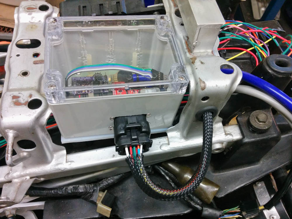
All the connections to the wideband controller/comm box are done. Looks quite neat with the Ampseal connector and the wire braid.
Moving to the back, it was now time to start connecting all the electronics. It’s quite difficult to know how long the wires need to be, but in most cases you can just cut them “long enough” and trim later. After a full afternoon’s work, the connector to my custom box is all wired up, and the result looks quite nice, if I may say so.
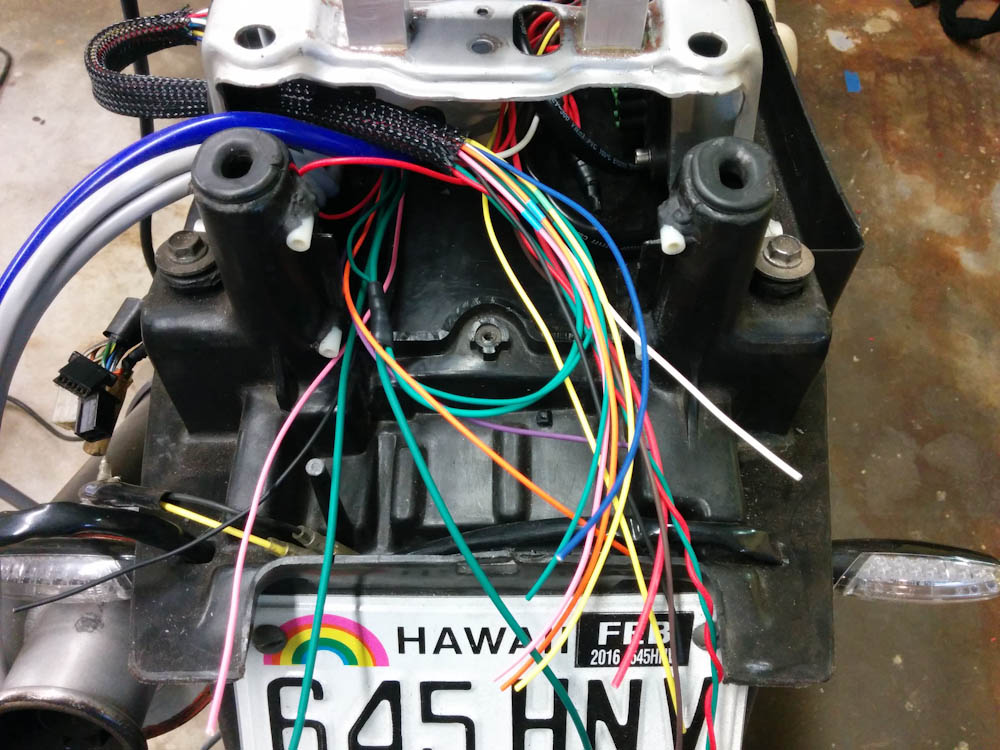
The Microsquirt wiring is still a complete rat’s nest.
Mostly, it’s now a matter of crimping and mounting all the terminals for the big 35-pin Ampseal connector for the Microsquirt. It may end up being quite tight in there, given that you probably want some slack on the wires. The final task is to connect the two oxygen sensor wires (the two thick, gray wires in the picture above) to the controller boards inside the box, and then I think I may be able to start it (using the stock ignition system.)
Pingback: Microsquirting the NC30, part #6: It’s alive! | Patrik's projects