The previous post talked about how we arrived at the present unpainted state. Before painting, there were some things to attend to with regards to the rear fairing. This is still the early Tyga version, and it also has some fitment issues.
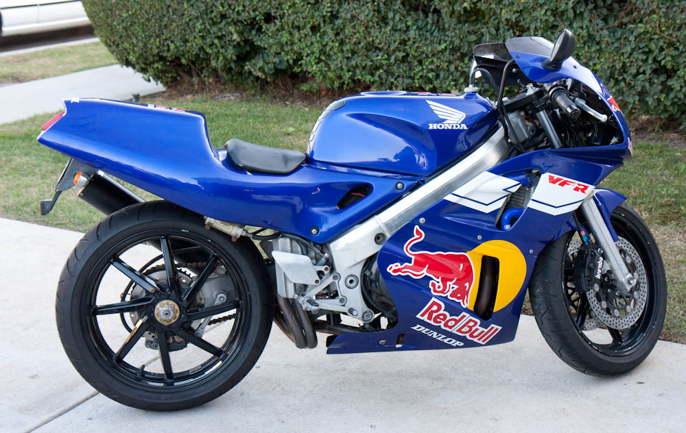
In case you don’t remember, this is how the bike looked when I bought it.
Look at the rear fairing above. The only places where it’s attached are with the four screws (two on each side) at the front end, under the tank, and where the front of the seat hooks into the tank. The entire part rear of the seat is unsupported! The rear end flexes easily an inch up and down when attached, with most of the flex happening at the rear end of the seat there the profile is the lowest. The paint is actually cracking in this area, presumably from being flexed continuously while in motion.
The second problem is that the screw holes don’t fit the frame (you should have guessed this was coming by now.) The distance between the two holes isn’t correct. When the front screw is attached, the rear hole looks like this:
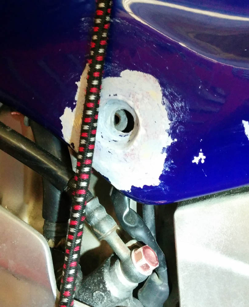
This is how the rear hole lines up with the mounting point in the frame. Or rather, how it does not…
When mounting this piece, you had to push the fairing hard to get the screw to thread in, and over time this side load had completely obliterated the threads into the aluminum frame. If I’m going to put in a bunch of effort painting this piece, I want it to fit properly. So after a bit of agonizing, I decided to trust my fiberglass skills and “get medieval on its ass” (in the unforgettable words of Marcellus Wallace):
After cutting out the old screw hole, I can now make a new one…. I hope.
The idea is to lay up a new mounting hole here, but in the right place. I’m not exactly sure what the best way for modeling the depression for the screw head is. Probably making a plug to fill the hole first, shaping its outer surface to the right shape. Then making a mold of that against the outside. We’ll see.
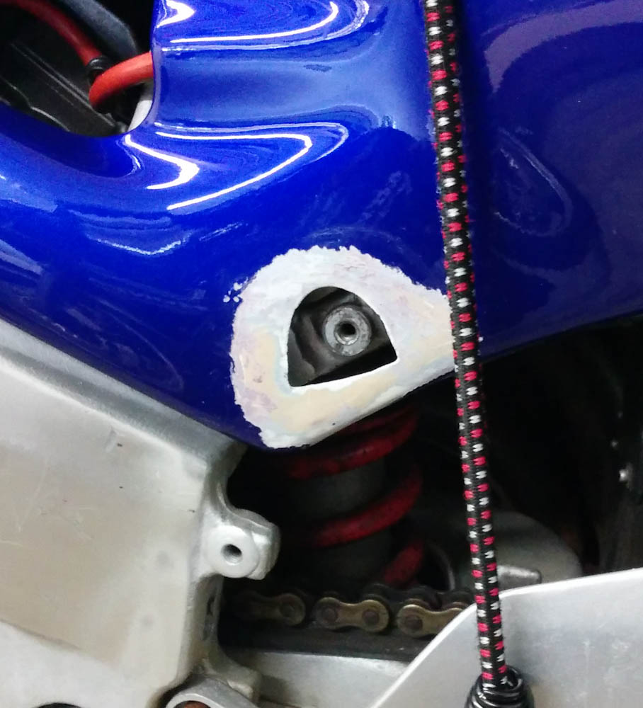
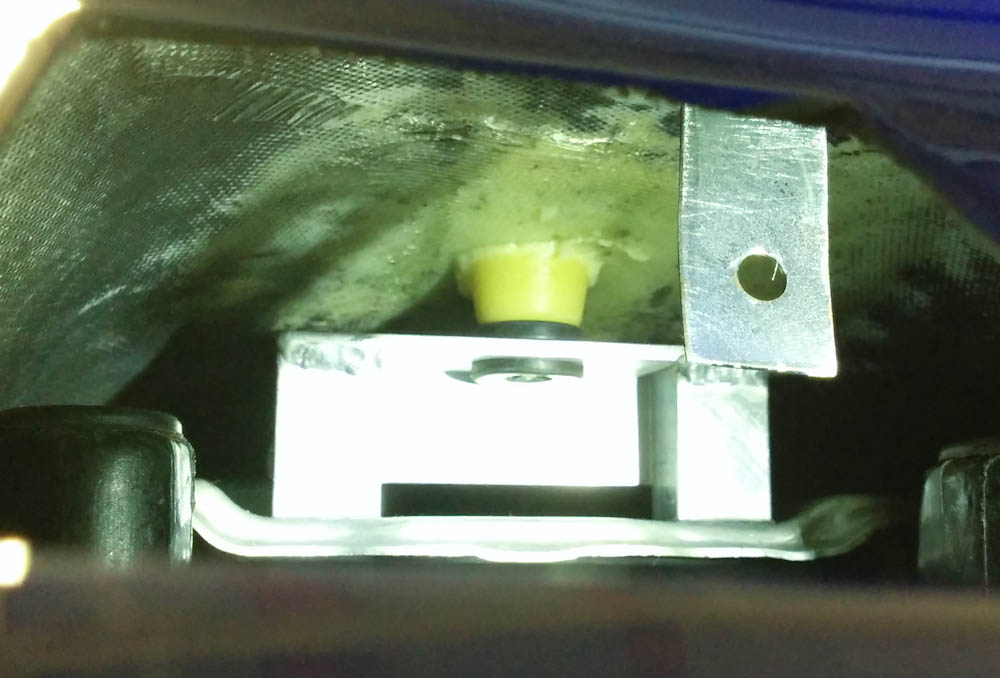
The other thing that I wanted to fix was to make some sort of support for the rear end of the fairing so it can’t move around. There are two steel rails on the subframe that are meant to support the rear seat. Since I don’t have a rear seat, I decided that I could add a support on top of the rear one and make the fairing key into a hole in it.
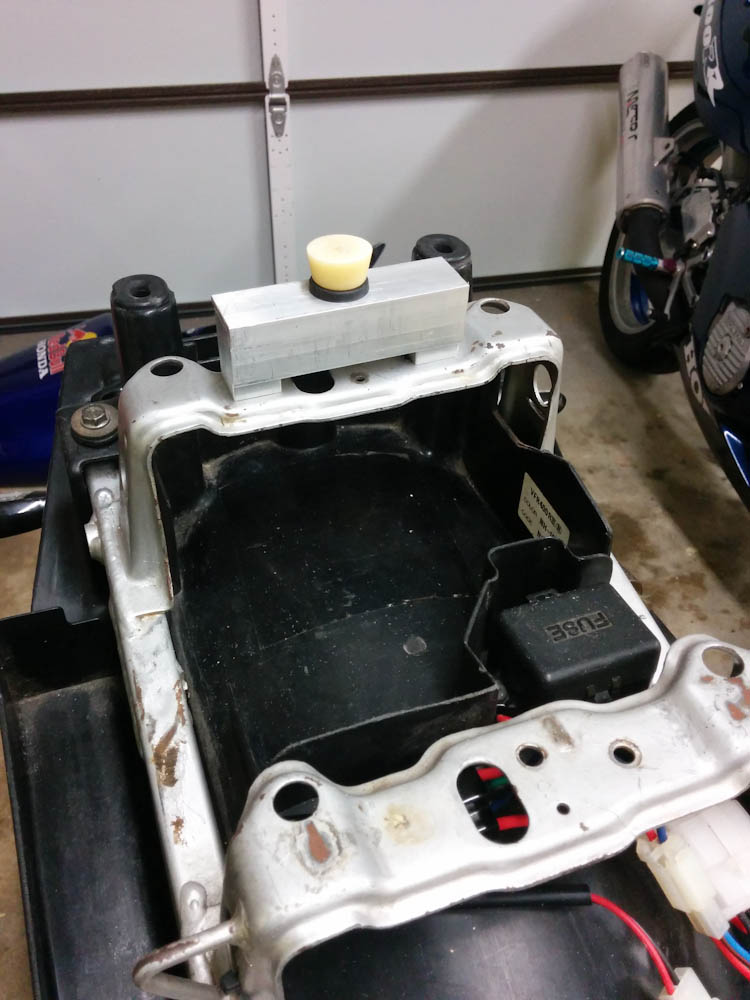
The short piece of aluminum angle on the rear bracket holds a grommet that a point on the fairing will key into.
I molded the “point” that will key into the grommet from the ones that are on the seat. They don’t match up with anything on my bike, so it’s not clear what they are for, but the shape was right.
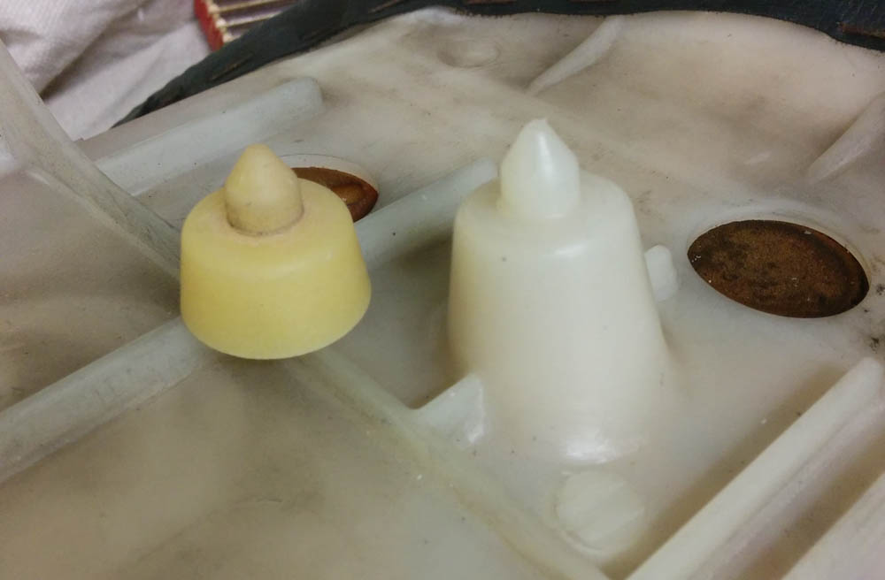
The “point” on the seat pad and the copy I made.
To make a copy of it, I first made a mold of the seat shape by covering it in Bondo. (Bondo is a polyester body filler that cures very quickly.) Once it had hardened, I could pop it off the seat, and I had a perfect mold for the part. Then I filled the mold with wet flox (epoxy and cotton fiber), which make a strong part. I couldn’t get the epoxy out of the Bondo without cracking the Bondo off, but that’s fine. It worked out very well.
For final fitment, I started by adding a couple plies of BID to the inside of the seat, after sanding it well. The fiberglass job on the fairings would make any Long-Ez builder weep — the top ply of fiberglass is so dry it looks like it’s just glued to the next one. In the corners, there isn’t so much an “air bubble” as the ply being completely lifted from the base, forming a cavity. This isn’t just the old part, the layups on the new front fairings look the same. I realize these aren’t structural parts, but come on…
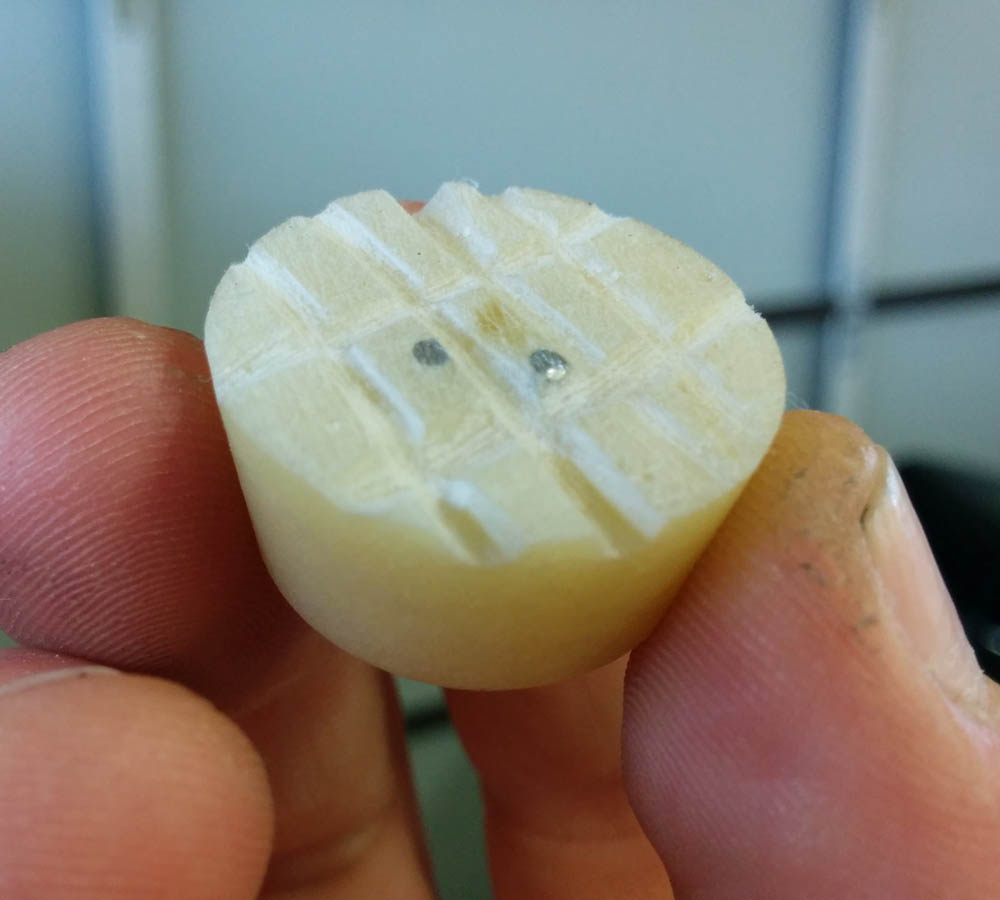
When attaching things with epoxy, it’s good practice to cut some structure into the surface so the epoxy has something to “bite” into.
To ensure that the point got into the exact right position, I then mounted the fairing by the front holes (the ones that are still there…). I cut some notches into the plug to make it adhere better, scraped a pile of fairly dry flox on top of it, and positioned it into place. Then the fairing was pushed down solidly onto it with some pack straps.
Here’s the point floxed in place against the inside of the fairing. This should securely position the back part of the fairing.
Now that the fairing is securely positioned both front and back, it should be possible to lay out the rear screw holes so that there won’t be any tension when mounted. Stay tuned.
Pingback: NC30 fairing job #3 | Patrik's projects
Pingback: NC30 fairing job #3 – Patrik's projects