Engine guts 7: More oil mods

The second step in the “oil mods“, after boring the case to increase oil supply to the left-side (in the airplane) lifters, is to modify the lifters themselves to increase the oil supply to the head.

As you can see below, the lifters have two circumferential grooves in them. One of the grooves has a hole in it, leading to the pushrod bore inside the lifter. When the lifter is not being actuated, the groove without the hole is aligned with the oil supply in the case. Oil will flow around the groove and on to the next lifter, and also oil the lifter bore.

The second groove, with the hole, is aligned with the oil supply when the valve is open. Oil will then not only flow around the groove but also into the hole and into the pushrod, supplying oil to the rocker arms in the cylinder head.

The problem is that this only happens when the valve is at full lift, which it is for maybe 90 degrees out of the 720 degrees of crankshaft rotation during an engine cycle. This means the head is only getting pressurized oil 1/8 of the time. This is the most important time for it to get oil since this is when the rocker arms are under maximum pressure, but experience has shown that it apparently is marginal and more oil is needed to ensure the rocker arms don’t gall, especially if you use high-pressure valve springs.

Furthermore, if an aggressive cam with lots of lift is used, it may even push the lifter groove past the oil supply hole in the case, in which case the head just gets a little blip of oil as the lifter groove passes the hole. Not good at all.

A lifter modified to increase the oil flow to the head. The hole in the upper groove supplies oil to the pushrod. The mod is to cut three connecting grooves between the two grooves, so that the one supplying oil to the pushrod gets a continuous oil supply even when the valve is not being actuated.

The fix, as shown in the picture, is super simple: You just grind passages connecting the two grooves. Three cuts, arranged roughly symmetrically around the lifter, in recommended. The biggest risk is letting the Dremel jump around on the lifter surface, but I managed to do all 8 lifters without any accidents. It only took maybe 15 minutes in all.

This way oil will flow to the head basically 100% of the time. This is supposed to not only decrease the risk of lubrication problems with the rocker arms, but the increased oil flow through the head also increases the heat transfer into the oil, since the cylinder heads are the hottest part of the engine. This should help cylinder head cooling (while increasing oil temperature, of course.)

The only possible drawback of these oil mods (which incidentally VW themselves incorporated into their next model, the Type IV engine) is that it may pump so much oil into the heads that there isn’t enough in the oil sump. I’ll monitor the oil pressure closely for signs of the pickup tube sucking air when we start running it again.

I also examined the wear on the lifters quite closely. While there the surface is noticeably worn, all 8 surfaces are still clearly convex. There is very minor pitting, as shown in the picture below. I was tempted to replace them since I don’t want to have to pull the engine apart again to change the lifters, but decided against it. I think they’ll be fine.

The lifter lobes have clear signs of pitting, but it is very shallow. The picture makes it look worse than it is. They can barely be felt when dragging a scribe over the surface.

The list of things that need to be done before the case can be put back together for good is getting shorter. Top on the list are balancing the new rods and pistons and verifying the cam timing. That’ll be the topic of the next post.


Engine guts 6: More head work

While working on the “oil mods”, I’ve also been trying to get the combustion chamber volumes more even, as I talked about two posts ago.

As so many other things, this became quite an ordeal. It turns out 2cc is a lot of material to remove. I’ve been grinding and measuring for what seems like days. I quickly realized I needed to start hogging out big chunks of stuff to get anywhere, but it’s hard to judge and you don’t want to make some gouges that are so large they can’t be smoothed out later.

The natural spot to remove material is around the extra spark plug, which now is quite unshrouded on the heads that had material removed from them. It’s a big difference compared to the original state, as you can see in the pictures below. This has lead to more shape differences than I liked but there’s not much to do about that. I’ll let the pictures tell the story.

This is the, basically untouched, largest combustion chamber, cylinder #2, with a volume of 67.5cc. As you can see, the spark plug is set quite deep into the head. The only thing done here was to grind away the threads visible in the aluminum, as well as the 1-2 threads of the Time-sert insert barely poking out of the head on top. This also provides needed piston clearance.

This is cylinder #3, which started out with a volume of 66.4cc. Comparing the location of the spark plug with cylinder #2 above, it’s obvious that it’s located much closer to the piston, which likely is the cause of most of the discrepancy. The cavity in which the spark plug sits has been opened up and rounded out to compensate. The area below the intake valve, on the left, has also been deepened to match that of #2 above. After this work, the volume has been increased to 66.9cc.

Cylinder #1, which initially started out as the smallest chamber at 66.0cc. In addition to having a “high” spark plug position like #3 above, also note that the secondary spark plugs, on top, are not mounted symmetrically. In this cylinder, it is toward the exhaust valve, while in the others above it is toward the intake valve. Because the chamber is asymmetric, this cuts the hole more “normal” to the chamber surface in this cylinder, which likely added to the difference. This chamber was treated in much the same way, except the spark plug cavity was made even wider. Even with this amount of work, the chamber has only been increased to 66.4cc.

At this point the chamber volumes are 66.4, 66.9, 66.9, and 67.3 cc. This is a spread of 0.9cc, which I’m going to call good since I’m really not comfortable removing as much more material from #1 as I already have, which would be the required amount to get #1 into better balance with the others.

I’m not so excited about this amount of discrepancy, and the asymmetry of the spark plug placement bothers me. I know it’s not by much, but it’s gotta contribute to uneven combustion between the two sets of cylinders.

While I had the heads and the Dremel out, I decided to do some work on the cooling passages. It’s extremely important that air can flow through the cooling fins around the exhaust ports. These holes are often blocked by casting flash and need to be cleaned out. I’d done some of this back when I had the heads at home for the spark plug thread repairs, but not as well as it should be.

After finding some pictures online about how the holes should look (and probably also having gotten over my hesitation of cutting into the heads) I went ahead and drilled most of the holes. The long “aircraft drill” used in the previous post came in handy here, since these holes are quite deep.

These holes were opened up drastically using drill bits. The exhaust port is right below them, so cooling is critical here. The small hole on the right goes quite near to the casting for the exhaust valve guide. There was no opening here before, and I probably had to drill through 5mm of material to break through. It’s not a big hole, but it should improve the cooling here a lot over the previous situation with no airflow at all.

Having “opened up” those holes, I got a bit innovative and figured I could make some holes near the exhaust flange, where there shouldn’t be any.

This is the area closest to the exhaust port flange, which did not have any air passages before. It’s not possible to go all the way through the head here, because the head stud on the other side is in the way. It is, however, possible to drill diagonally. (Sorry for the bad picture, it was hard to get sufficient lighting here.)

This view shows the other end of the hole near the exhaust flange, and also makes abundantly clear that drilling straight through the head was not an option. The red RTV line to the right marks where the baffles go, so this hole will exit on the low-pressure side of the baffles, as it should.

Hopefully enlarging these holes will provide some sorely needed improved cooling to the exhaust port area of the heads.

While reading about where there should be air passages in the heads, I also came across an interesting note by Bob Hoover. The area between the cylinders has a fairly large air passage, without fins, seen below.

This rather large hole allows a lot of air to pass through and exit the bottom of the head without doing much cooling.

Apparently on the stock VW heads, there is a blocking plate in this location, forcing the air to spread left and right through the cooling fins on the bottom of the head rather than just go straight through. I have not seen this described anywhere else, it’s certainly not part of the Aerovee instruction. It makes sense, though. It should look something like shown below.

I rough-cut a piece of aluminum plate to the required size to see how it would fit. The fins have a square-shaped depression that indicates that there really should be something here.

By forcing that air to take a more useful route, it will accomplish two things: First, it will do some cooling work. Second, because it will encounter more flow resistance, it’ll increase the overall air pressure above the engine which will help push more air through the smaller passages. (Unless we have a big-ass air leak somewhere else, that is.)

I’ll certainly go ahead and add plates on our heads in this location when replacing the heads. It should be simple to cut squares of aluminum sheet and RTV them in place on the fins.


Engine guts 5: Oil mods

I finally got the “aircraft drill bit” (which is a very long drill bit. Why they are called that, I don’t know) needed for the modifications to the oil delivery in the engine case.

Apparently, type 1 VW engines have marginal oil supply to the rocker arms in the heads. Oil gets there through a circuitous route through the center camshaft bearing, to the lifters, through the pushrods, and into the rocker arms. The first problem is that rather small oil passage through the cam bearing. People have long since figured out (like 50 years ago) that you can double the supply by drilling through the case to the cam bearing on the pulley end, too.

At least most of the time, you can. There’s apparently manufacturing differences in the castings that make it so that if you try this on some engines, you’ll drill out through to the outside of the case instead, basically ruining the case. After measuring a bunch of times, I convinced myself that it would be OK on our engine.

This picture shows the basic idea. The 12″ drill bit is inserted from the flywheel end of the case, which has been drilled through all the lifter holes. The lifters get their oil through the hole in the cam bearing saddle in the center,, which is supplied with oil from the other side of the case. The idea is to extend the holes through the lifter bores to the right, and then extend the other hole in the cam bearing saddle on the right to intersect with it. While the hole in the bearing saddle is quite large, note that it is only supplied with oil through the small, square passage cut in the bearing surface.

There are two intersecting holes you need to drill to complete this operation. Both have the potential to ruin the case. Starting with the long drill bit, you extend the holes through the lifter bores as shown in the picture above. To ensure you don’t drill enough, the required depth of the hole is carefully measured and marked on the drill bit.

As I was drilling this hole, the bit made a sound that sounded like when you break through the surface. Which it wasn’t supposed to do! Envisioning dollar bills flying off, I turned the case over but found no hole. It must just have been porosity in the casting. I bravely continued drilling the few more mm needed, without incident.

Next step was to extend the hole in the cam bearing web. Here you’re really drilling straight towards a pocket in the outside so it’s really important to not go too far. Ideally you’d break through to the first hole before that happens, but just to make sure I marked this drill bit with the required depth, too.

Success! After drilling into the cam bearing web, the tip of the long drill is visible through the hole. Next step is to widen the small, square hole in the bearing surface.

Aiming towards the extension of the holes in the lifter bores, it didn’t take long to indeed break into the other hole. Phew. Now the lifters on this side of the engine has twice as much oil supply as they did. To further improve the oil supply, the square passages in the bearing surfaces were also widened a bit.

This drill operation was the final step I’ve been waiting on before all-out cleaning the oil passages from the swarf left over from fitting the Force One bearing and tapping the case for the oil plugs. Using a spray bottle of mineral spirits, I flushed out all the passages, as well as the cavities on the inside of the case. It was pretty cool, the tub I was using was shimmering with flushed out suspended metal flakes! After blowing out all the passages, it was inspection time.

This is the bore for one of the oil pressure control pistons. Looks clean.

This is the main oil gallery supplying the crankshaft and camshaft bearings. Looks nice and clean.

This is route to the oil cooler. This one had some stuff left in it that needed to be cleaned out.

Overall things looked pretty clean. I found a few passages that had little bits of crud in them that had to be brushed out with a pipe brush, but we should now be good to put in all those plugs again.

With that, the case got some paint touch-up since all the handling since it was painted had chipped paint off exposed parts.

That completes the work on the engine case. Part two of the oil mods is to modify the way in which the lifters supply oil to the pushrods. More on that later.


Engine guts 4: Blueprinting

Things are slowly proceeding on the engine front as I’m meticulously going through some things while waiting for parts for others.

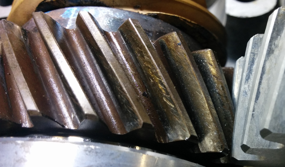
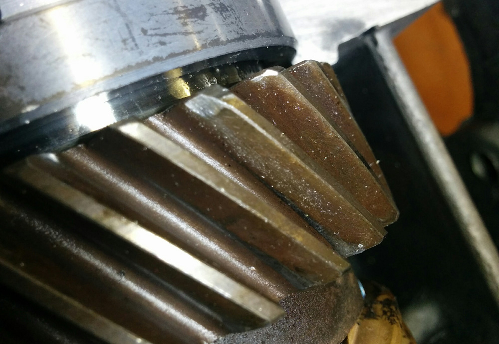
I got the cam gear thrust bearing endplay, mentioned in the last post, set right only to realize that this added to the free play in the gears (they are helical, so end play translates to angular play; or maybe it was just easier to notice once the cam turned more freely) to the point that it was outside of the spec. I’m banking on this being because the aluminum cam gear is worn, so I ordered a new one from CB Performance. The cam gears are supposed to be available in different sizes to account for tolerances in the spacing between the crank and cam shafts, but it appears most aftermarket parts only make the “0” standard size. If a new gear doesn’t get the play within spec, I guess I have to go searching harder.

Next topic on my rather long list was to balance the connecting rods. This is a bit tricky, because you can’t just ensure they have the same mass. Because the big end of the rods is rotating with the crankshaft while the small end reciprocates with the piston, they also have to have the same center of mass (and, I guess, also moment of inertia, if you want to go all out). This is accomplished by weighing the small and big ends separately, which requires a jig to hold the two ends such that you can put one on the scale and it can rotate around the other.

After looking at some of these setups I realized I had some small ball bearings left over when I replaced the bearing in the anemometer on the weather station that could be put to use. I designed a simple setup in Fusion 360 and 3D-printed it in polycarbonate.

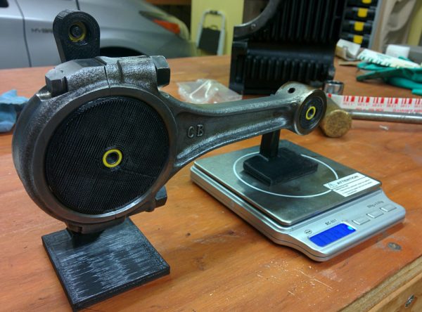
This is the 3d-printed connecting rod scale. There are two round bushings, made to fit the small and big ends, with two ball bearings each. The non-weighed end hangs on an extra link to minimize sideloads imparted on the scale.

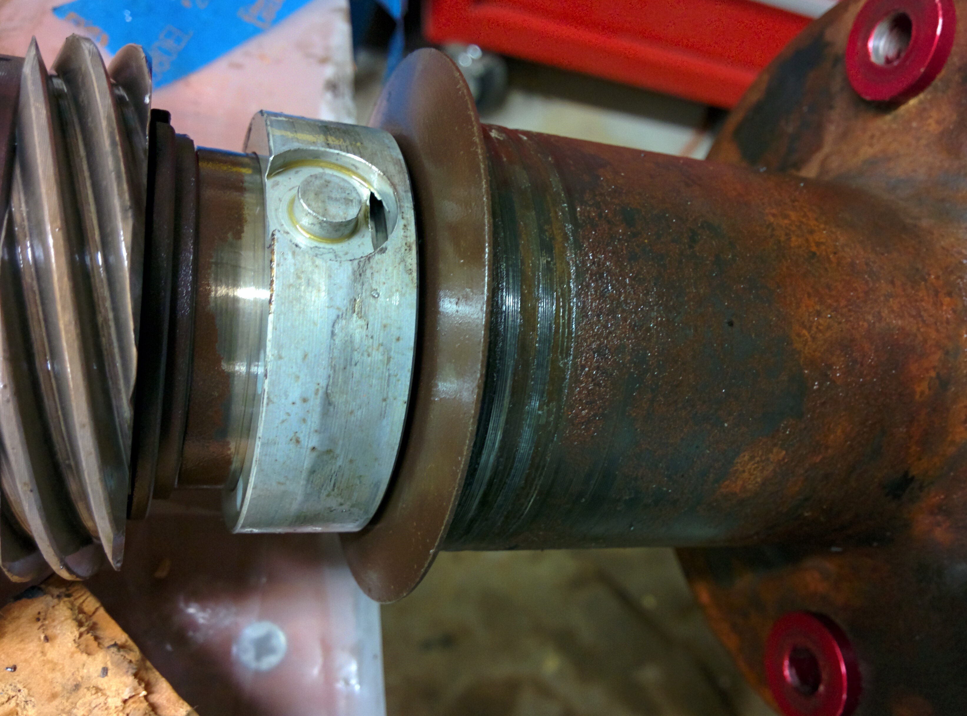
I initially had tried to weigh the small end by mounting the rod on the crank bearing and letting it rotate around there. This did not work, the oil in the bearings apparently has enough viscosity to affect the weight enough to make the measurement useless. A reasonable standard to set is to make sure the rods are balanced to within 0.1g, and the measurement error was several grams.

The new setup worked much better. There is still enough variance that you have to make a bunch of repeated measurements. I think this is because the scale is sensitive to side load and there’s enough flexure in the plastic setup to make it a bit non-repeatable. The scale, with a resolution of 0.01g, also turns out to not be repeatable to better than about 0.1g when you start repeating measurements, even without the side load issue.

The maximum difference between the rods was about 2g (out of ~540g). That’s not bad, but we can do better. With some careful grinding on (hopefully) non-critical parts of the rods, and many measurements later, both the small end and overall weight spreads were reduced to +-0.15g at which point I called it a day.

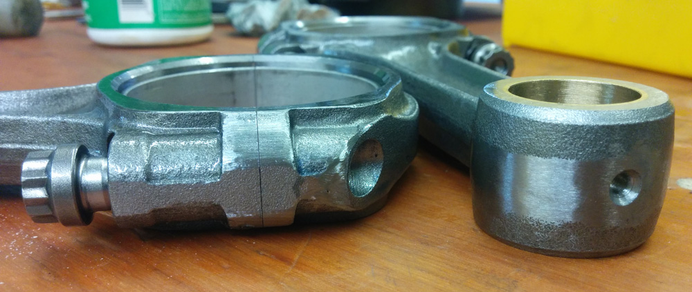
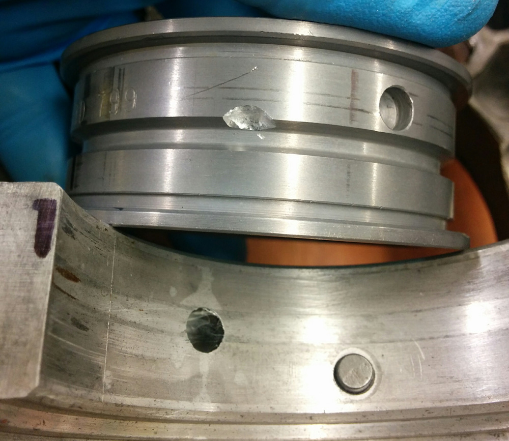
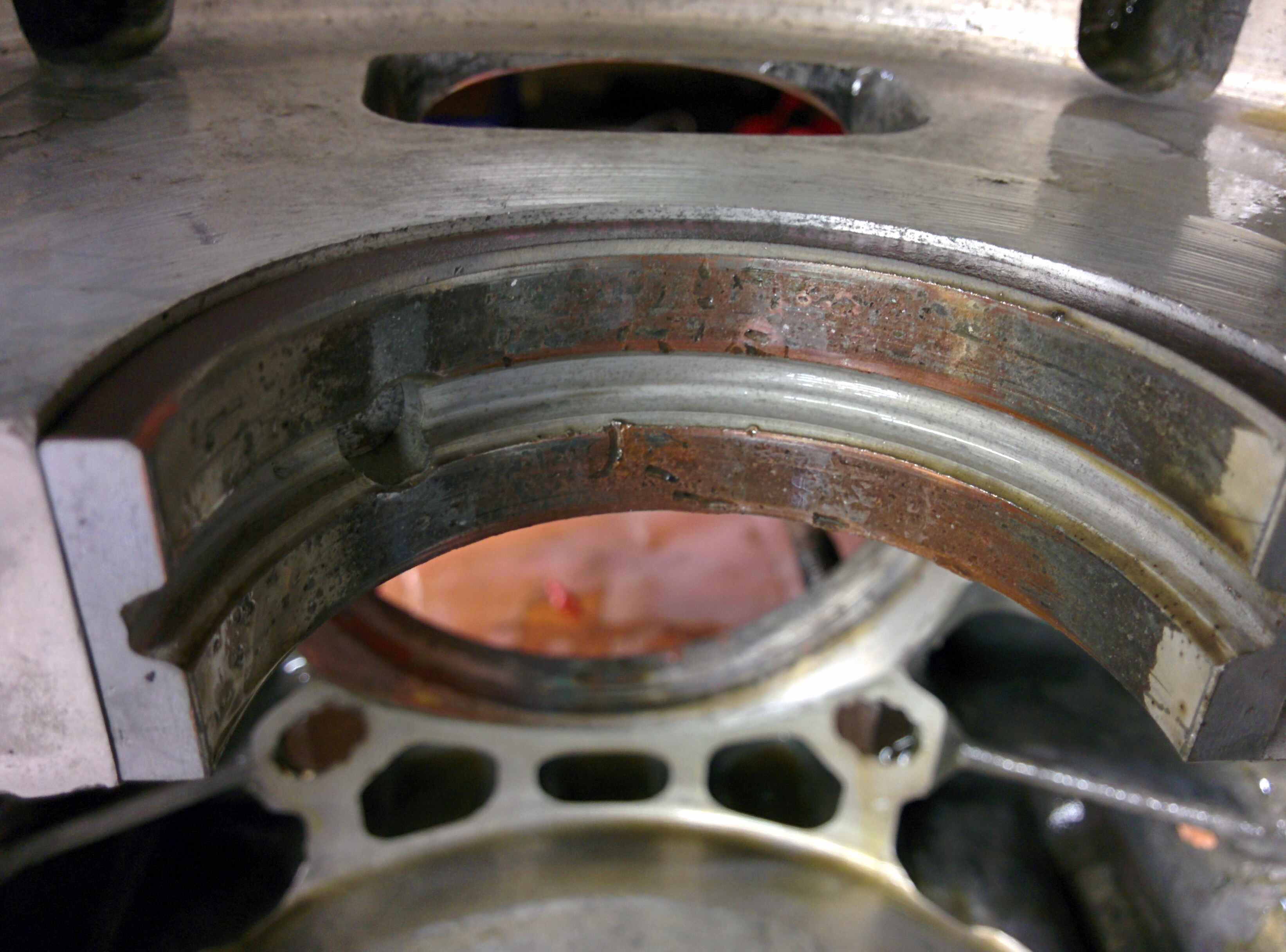
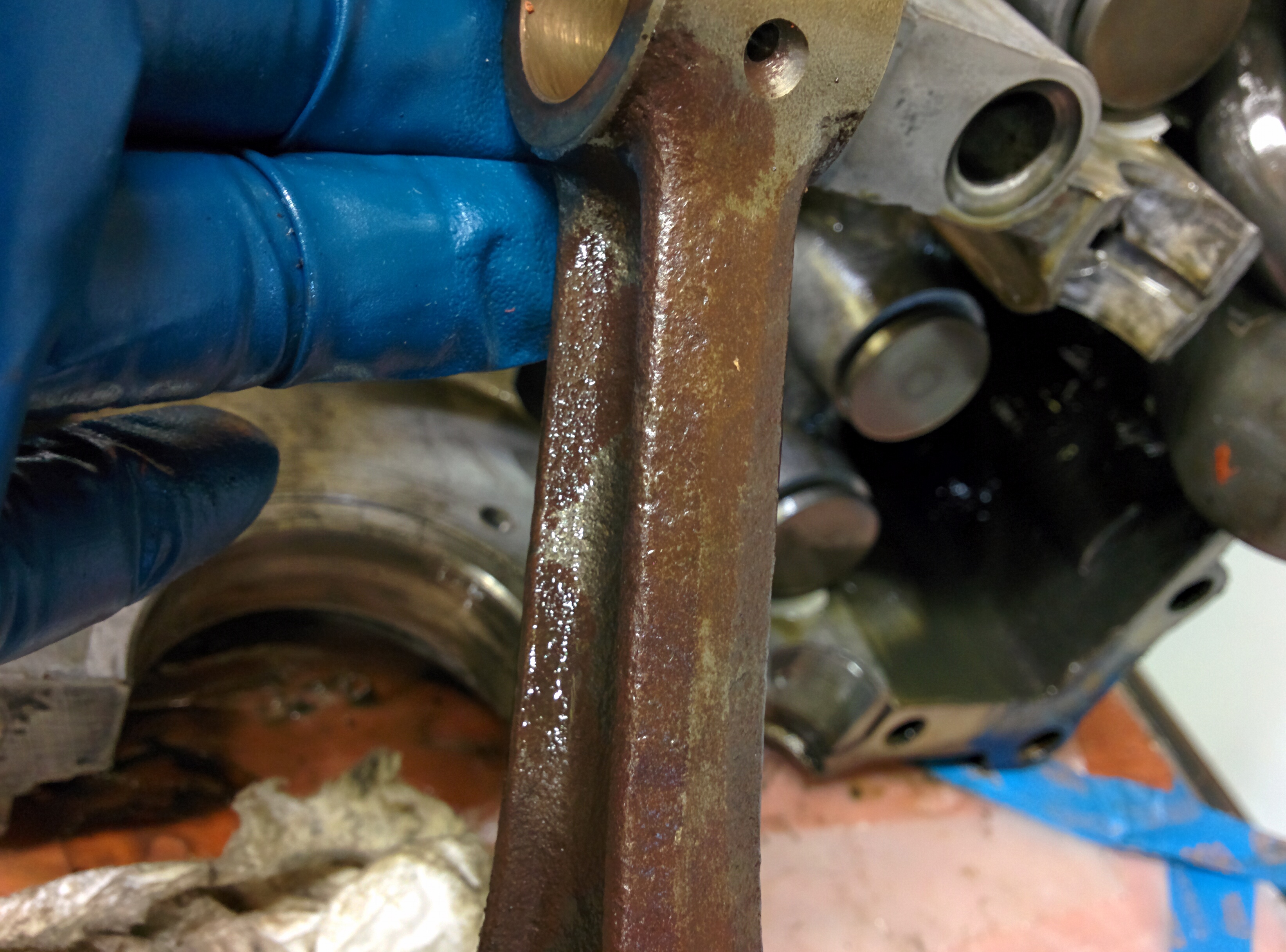
However, it turns out that was for nothing. I did measure the big end bearing clearance on one of the rods using Plastigage (I haven’t used my set in years and it turns out it was all broken and missing, but I got one last measurement out of it) but I had not looked at the small end. The “How to rebuild your air-cooled VW” book says that the wrist pin should be a light push-fit in the small end bushing, without any perceptible play. Turns out my rods failed that test. Given how much play the old crank bearings had, it seems reasonable that the rods saw more side loads and coned out the small end bushings.

In the “good old days”, this would be fixed by pressing in new bushings and reaming them to size for the wrist pins. This is one of these things that are no longer economical to do when a new set of rods cost $150, you don’t get much shop time for that. So I ordered a new set of SCAT rods that are supposedly already balanced to within 1g. We’ll see, but hopefully I won’t have to do a lot of grinding there.

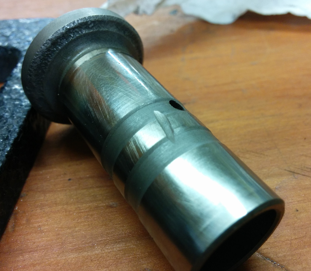
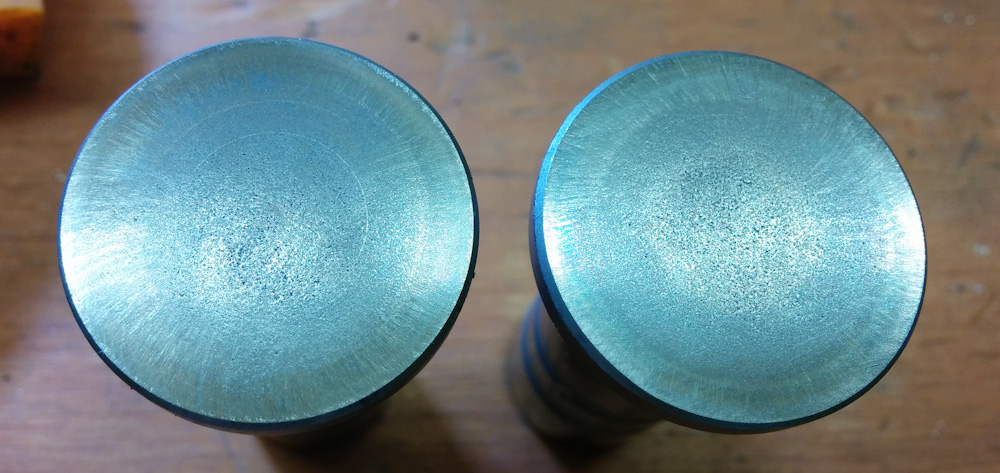
The other things that was supposed to get balanced was the pistons. The spread there was about the same, a couple of grams. However, in this case I started out measuring the ring groove clearances and discovered that at least a couple had bent or damaged ring lands, so we’ll be getting a new set of those too.

The old pistons were “AA” brand, so I ordered a new set of those. Turns out they make both a forged and a cast model, but the good people at aircooled.net claim the cast pistons are fine for engines that stay under 6500 RPM, which we do by a large margin. Since the forged pistons are about 3 times as expensive as the cast ones, I think cast will be fine.

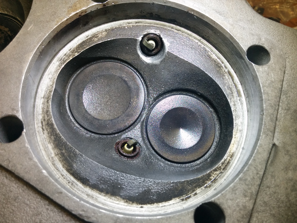
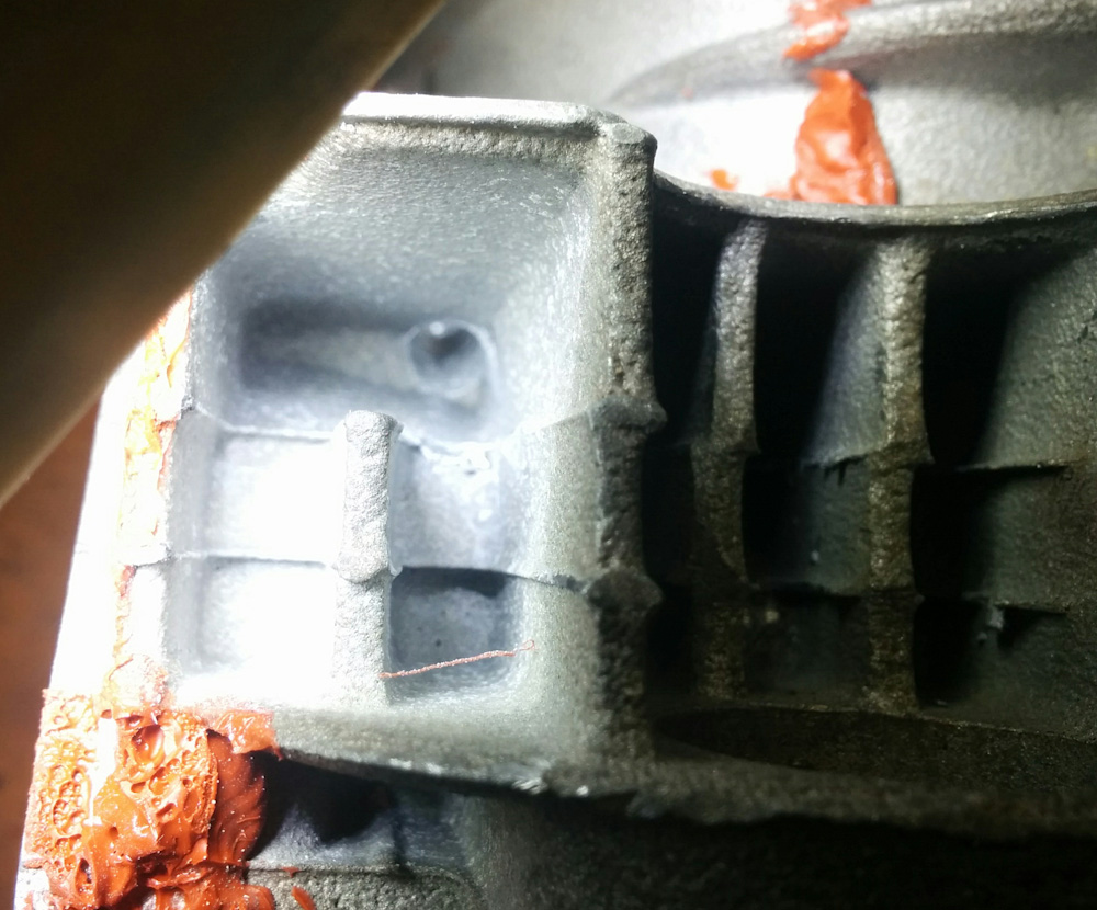
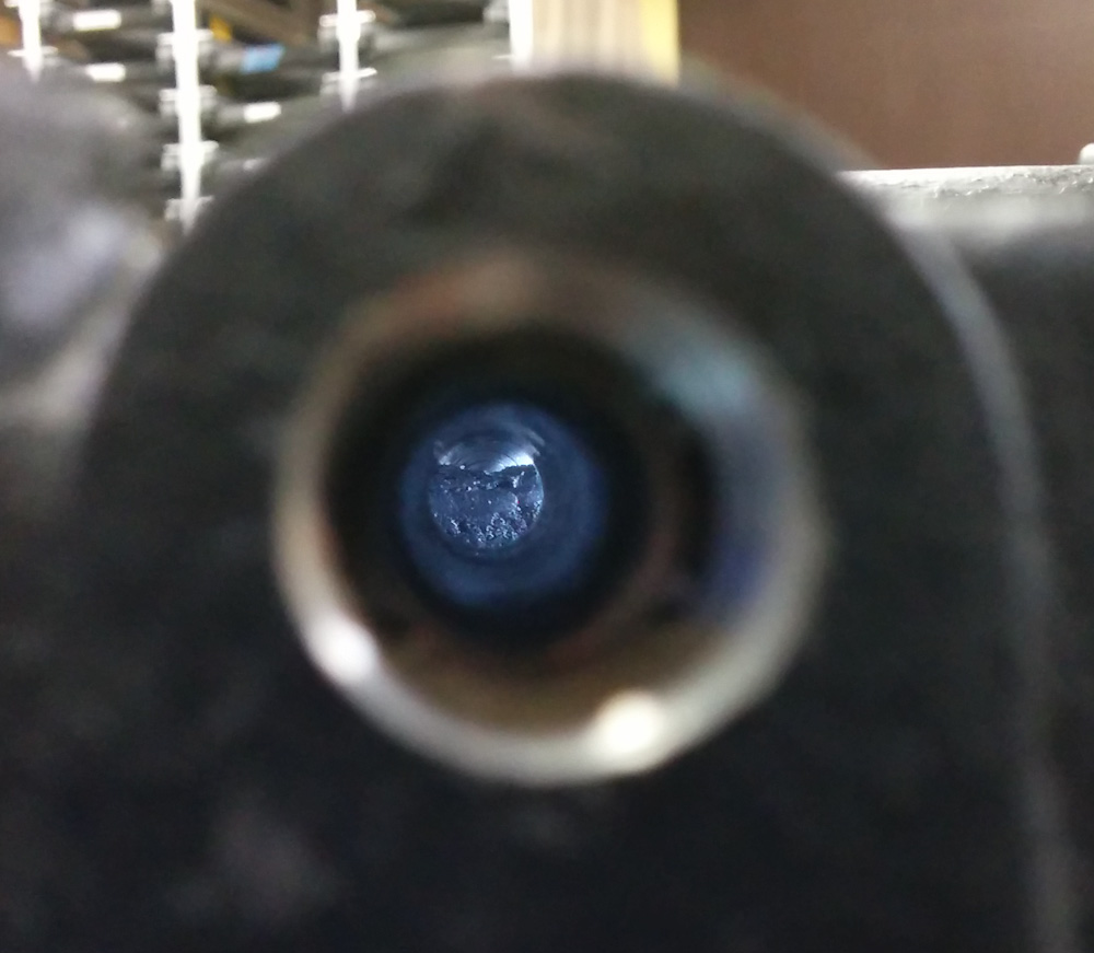
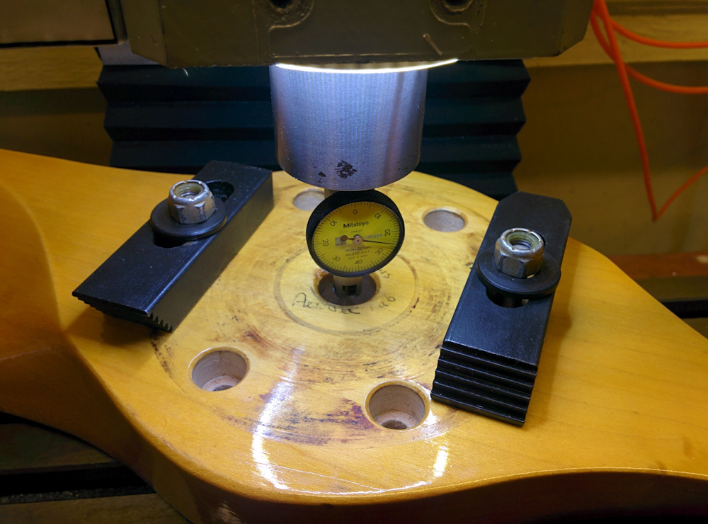
Moving on to the next item on the list: checking the combustion chamber volumes. If the combustion chambers aren’t the same volume, the different cylinders will run at different compression ratios and generate different power, contributing to uneven and inefficient running. Measuring the chamber volume is easy in principle. Cap the chamber with a piece of transparent plastic and fill it with water until it’s full. In practice it’s a bit more tricky.

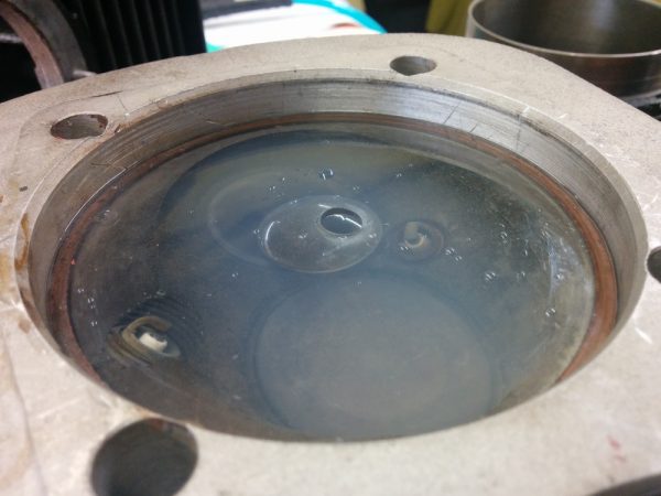
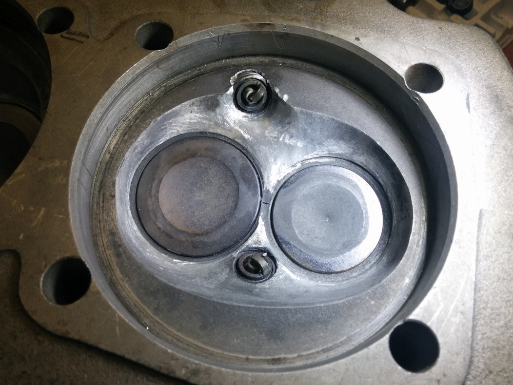
Measuring the volume of the combustion chamber requires a bore-sized piece of plastic and a way of measuring volume. This chamber is almost filled with soapy water

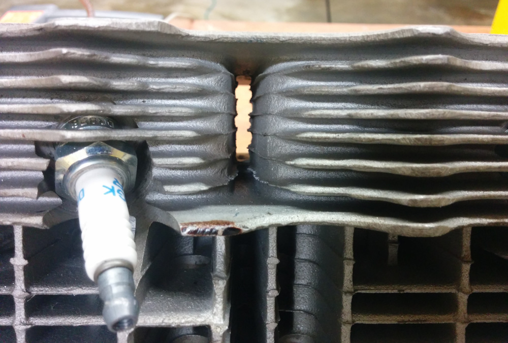
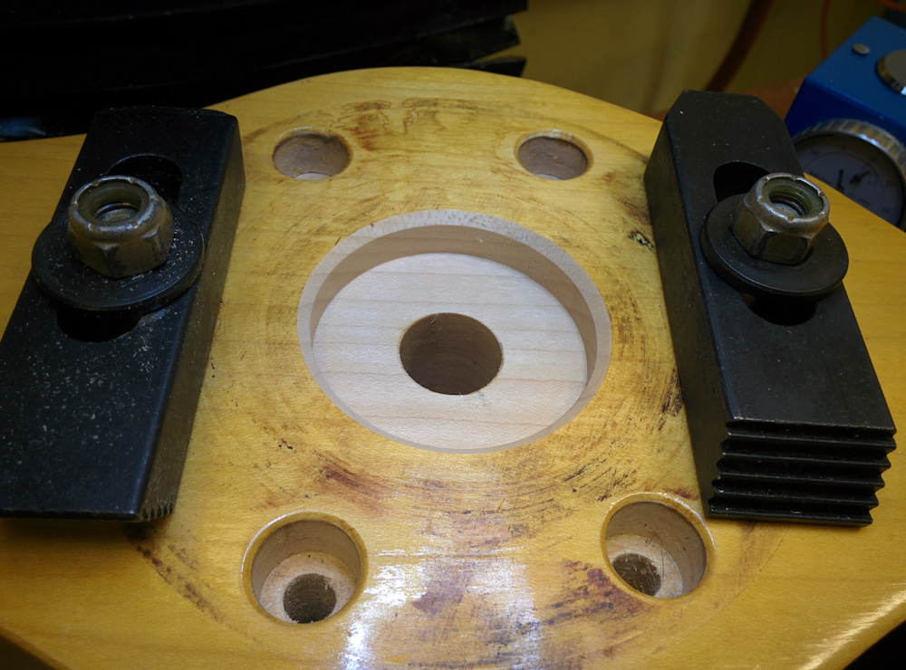
Normally when doing this on a VW, you plop the plastic directly on top of the head. This allows you to just measure the volume of the chamber without the squish areas where the full bore is exposed. This volume is easily added later when you measure the deck heights, ie the minimum distance between the piston and the top of the cylinder. On the Aerovee heads, however, the second spark plug protrudes into the squish area, so it’s not possible to put the plastic directly against the top of the head. I had to use the 1.5mm copper gasket ring as a spacer. This is fine, I just have to take that into account when setting the compression ratio later.

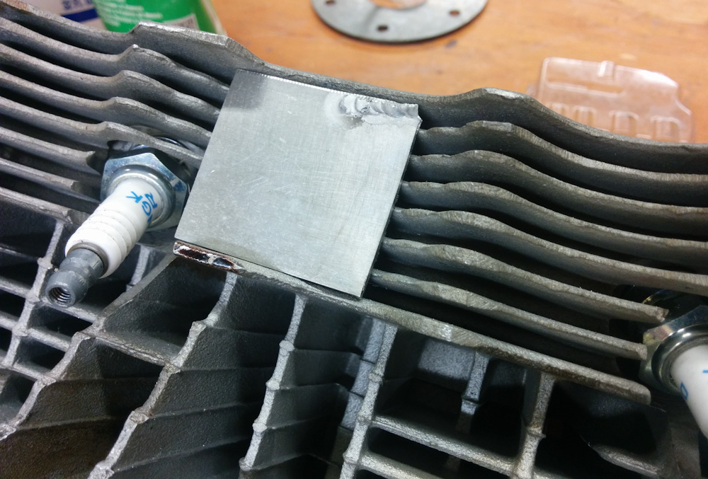
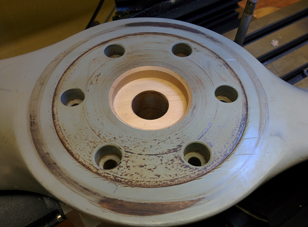
There were two things making this procedure trickier than I hoped. First, I discovered that using soapy water worked much better than clean water, because the surface tension of the water otherwise prevented it from wetting the spark plugs and other small cavities. Second, It’s quite tricky to get all the bubbles out. In particular, air tends to get trapped in the narrow squish area and it’s hard to get it to come out to the hole in the middle. You also can’t tilt the head indiscriminately since then water will seep out around the perimeter. To get as good of a seal as possible, I coated the edge of the plastic with grease and set one of the cylinders on top of it to ensure it was pressed against the gasket.

I also don’t have a good way of measuring volume with high accuracy. Instead, I used the same precision scale and weighed how much water I had to take out of a cup and squirt into the head. This is a bit more error-prone since you have to ensure you don’t lose any of the water anywhere else. In practice, I repeated the measurements three times and got a spread of about 0.2cc, well within the accuracy needed. The chambers are about 68cc and with a swept volume of 545cc per cylinder, being off by 1cc results in a difference in compression ratio by about 0.12. It should not be a big problem to reduce the existing spread of about 2cc to less than 0.5cc.

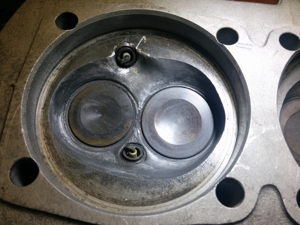
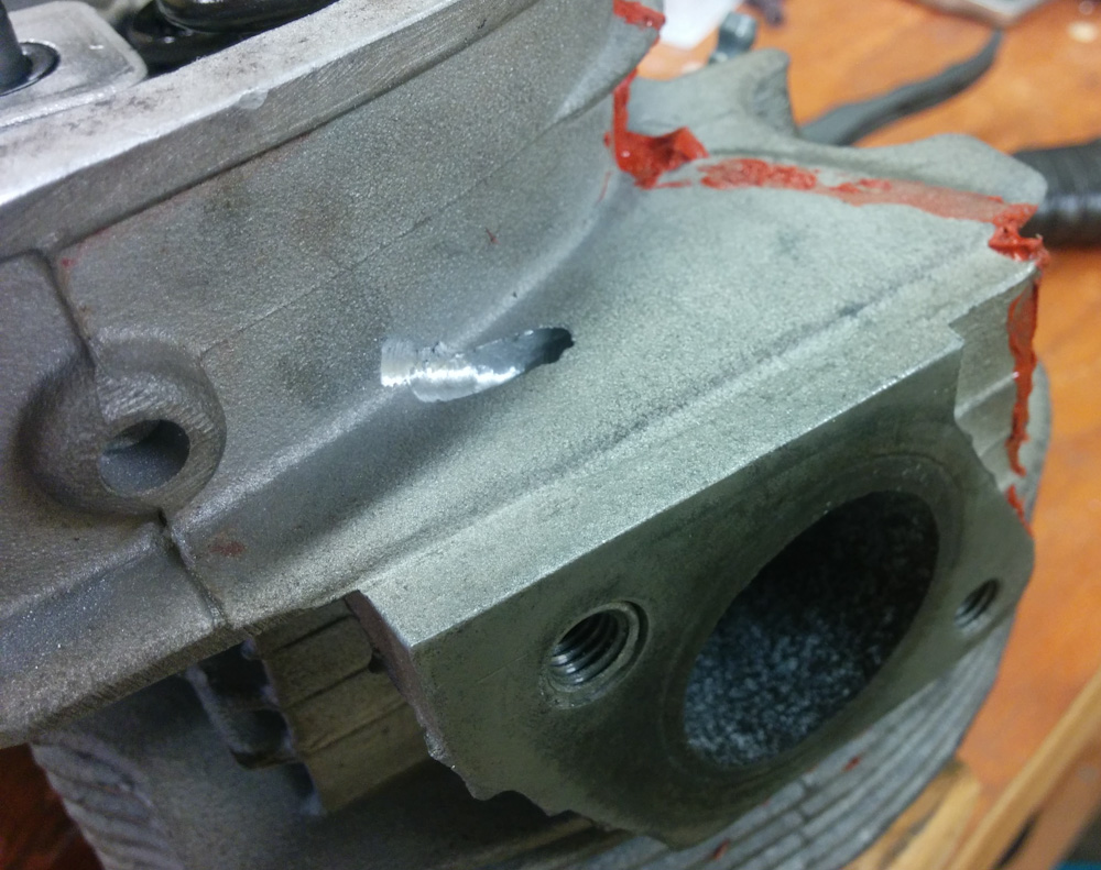
Once the volumes have been measured, you of course have to do something about it. The obvious solution is to grind away material from the chambers with smaller volumes until they are equal to the largest one. But where do you grind? It appears with these heads, the differences are mostly from how deep the seat for the extra spark plug was cut, so it seems reasonable to take out material around that area. This should have a minimal effect on the airflow through the chamber, since you don’t want to end up making that uneven between the different cylinders either.

I’m currently in the process of modifying the chambers, so I’ll report back when this is complete.


Engine guts 3

I finally got the engine case back from the machine shop, so I could proceed with remaining work.

First I finished up drilling out all the oil passage plugs from the case that my Dad and I started before giving the case to the shop. To be 100% sure that you get all gunk and swarf out of the oil passages, you need to remove all the plugs from the case and instead tap them with assorted NPT pipe threads so they can be replaced with screw plugs at assembly.

This task was straightforward except that the largest passages use 14mm plugs that need to be drilled out and tapped for 3/8″ NPT thread. The drill for such a tap is just over 14mm, and the only place I can mount such a drill is in the drill chuck for the CNC mill. The CNC mill, however, doesn’t have enough space to fit the engine case, so that was not a solution. I ended up using the Dremel to get rid of most of the material from the inside of the existing hole (always fun) and then turning the drill bit by hand to let it cut the hole to size. It took about 20 times longer than if I had been able to just drill it, and the holes did not come out perfectly perpendicular. That is luckily not a concern since all you need is for the tap to cut a usable thread, which it did.

The Dremel added to the significant amount of swarf still left in the case from the machine shop cutting it for the prop hub bearing, but I only cleaned it out superficially since I still have one more drilling operation to complete. I need to drill out an oil passage to improve oil flow to the heads, but that task awaits the arrival of a 12″ long drill bit.

Instead, it was time to test fit the crankshaft and make sure the machine shop hadn’t screwed up the job. The first order of business was to make sure everything was in-line and the crankshaft wouldn’t bind in the bearings. Before fitting the crankshaft, I started by bolting together the case halves and measured the bearing bores with my just-acquired cheap set of bore gauges. These require a bit of skill to use accurately, but in combination with the Mitutoyo digital caliper the bores generally came out to 50.03mm, plus minus a few hundreds of a mm. That’s in the right ballpark, since the service limit turns out to be 50.03mm, but the as-new dimension is 50.00-50.02mm so I don’t really have the required amount of precision here. But at least there was no sign that the bores are grossly oval or oversized, so that’s good.

When trial fitting the crank, you replace the locating dowel pins, mount the #2 bearing half (the other bearings are full-rounds so are slid onto the crankshaft) and then lower the crank in place, taking care that all the bearings find their dowel pins correctly. At that point, the crank should spin freely. Which it did, kinda. Not as freely as I would have hoped, but only finger force was needed.

The real test is to do this with the case halves bolted together, though, because the stud tension actually deforms the case. Boring is always done with the case bolted together to the correct torque, so in principle the bearing bores aren’t circular until things are tightened down. This actually turned out to be the case now; as the studs were tightened the crank spun progressively more freely. Kind of cool. This included the new Force One bearing, so apparently the machine shop did their job.

The engine case with the new Force One bearing up front, bolted up and with crank and cam shafts test fit.

The next step was to add the camshaft. Here things looked a bit more iffy. First, the gear driving the camshaft has a lot of scoring on the teeth. I assume this also is from all the particles embedded in the oil.

The gear driving the camshaft has some knarly looking wear and scoring. However, it does not have excessive backlash so it seems OK.

The second problem was that when I added the camshaft in its bearings and tried to spin it, it would bind at a few places. Turns out that a few teeth had gotten dented on the edge. I suspect the shop did this when they pressed the gears off the old crankshaft. To get things to rotate smoothly, I had to dress the affected teeth with a file. No big deal.

A few of the teeth on the cam driving gear were banged up such that it would bind against the cam gear. Minor dressing with a file got the raised parts back in line so the gears meshed cleanly again.

Another little thing I was alerted to by a youtube video was the fact that the thrust bearing’s oil supply hole is not very well aligned with the oil passage in the back of the bearing, such that about half the oil supply hole is blocked. The solution to this is to simply grind away the back of the bearing to open up the hole.

As is visible on the thrust bearing journal, the supply hole is offset from the circular groove on the back of the thrust bearing. By grinding away the back of the bearing where the hole enters, the obstruction is minimized.

There are a few more things to sort out with these bearings. There is still a little binding when rotating the crankshaft/camshaft in the assembled case. It’s possible there’s another buggered tooth on the gear that I didn’t notice before. It’s also possible that this is because the thrust bearing on the camshaft has no end play. This is apparently a common problem with the bearings you get these days; they’re all too wide such that they actually stick on the camshaft. The solution is to carefully sand down the thrust surfaces of the bearing halves until the requisite 0.04-0.10mm appears. If you don’t do this, the bearing will not get sufficient lubrication.

Once these issues are worked out, it’s time for the rod bearings. Hopefully before the weekend.


Fitting the propeller

Along with needing to machine the engine case to fit the Force One bearing, there was one additional task needed to fit the propeller to the new hub. The Aerovee hub centers the prop on six bushings around the bolts, while the Force One hub has a 2″ centering pilot. Neither of our two propellers, which were manufactured for an Aerovee hub, had such a pilot.

We consulted with Sterba and Sensenich, who basically said that, if we sent them the propellers, they would just cut out such a pilot centered on the existing hole. At that point we decided that if they’re just going to mill it out, we can do that ourselves. Setting the prop up in the CNC mill and dialing in the center of the hole to 0.1mm should not be a problem, neither cutting a 2″ diameter hole in wood.

I started with the Sterba (since it’s 1/3 the cost of the Sensenich…)

Dialing in the center of the existing hole in the Sterba prop. This was first done with an edge finder, and then the dial test indicator mounted in the spindle to verify. The hole isn’t perfectly smooth (it’s wood, after all) but centering within 0.1-0.2mm was not a problem.

After the coordinates were zeroed on the center of the hole, it only took maybe a minute to run the program that cut the hole. For good measure, I added a generous chamfer.

After running the program, we have a nice-looking 2″ diameter hole.

Since it worked so nicely on the Sterba, I continued with the Sensenich. Here, it was needed to shim the bottom of the prop slightly to get the top to be flat. I don’t know if that’s related to the fact that it was slightly crushed or just the normal tolerance of the parallellism of the front and back face.

The Sensenich prop, also finished. This is the first time it’s unequivocally visible that it’s actually made of wood under that urethane coating.

So milling into $1500 worth of propellers was a bit nerve-wracking, but went well. I finished up the work by adding a thin coating of varnish to the exposed wood.

When I tried to mount them on the Force One hub, the center pilot fit snugly. However, I could not push the bolts through their holes due to a mismatch between the holes in the wood and the hub. I initially thought maybe the hole had been incorrectly centered after all, but even if I pulled the hub off the center pilot, the bolts did not fit. It also could not be the fault of the hub, because they didn’t fit the Aerovee hub either.

The nature of the mismatch was that the holes along the grain (in-line with the blades) fit well, but across the grain, both props were too large by maybe half a mm. Given that wood changes dimensions significantly when the humidity changes, I assume this mismatch is because the holes were drilled when the wood was drier than it is today. After a bit of Googling, I actually found a paper that had studied this exact thing on Sensenich props that were shipped to the Middle East for use on UAVs. The paper even has a table of equilibrium moisture content of wood at different relative humidities. At the average RH of maybe 80% we have in Hilo, wood has 16.5% water, but at 40% it’s only 8%. The dimensional change of the hole distances across the grain in the study was over 5x compared to the holes along the grain, and would correspond to about 1mm in radius on our props.

The installation instructions for the Sensenich prop don’t mention anything about hole positions changing, only the hub thickness, but it turns out those from Sterba do.

“Because of the slight differences in prop hubs and spinner bulkheads, it may be necessary to lightly file out one or more bolt holes in the propeller.”

So that’s what I did. I first used a stainless steel pipe brush chucked in the cordless drill to clean out the holes good, then carefully filed the holes with a round file until all the bolts would go in and not bind. This took quite some time, I probably spent about three hours repeatedly filing, trial fitting the hub and bolts, noting where they were binding, and filing again.

While no installation instructions mention this, it seems important that the bolts not bind in their holes since this both makes it hard to torque them accurately and also prevents the tension from being transmitted to the spinner. As they settle through vibration and temperature changes, they would then lose torque, presumably when the engine is first started up.

Anyway, it all seems good now. It would be good to balance the prop, but you really need to balance the entire hub and you can’t mount the prop on the hub before mounting the hub to the crankshaft, so I don’t know how to do that except with one of these fancy dynamic balancers that we don’t have access to.

The Sterba, trial mounted onto the Force One hub after filing the bolt holes. The Sterba prop is a beautiful piece of workmanship. The wide journal on the hub is for the large “front” bearing this hub uses.

Now if we could only get the engine case back from the shop…


Engine guts part 2

Over the last month, posting has been sidelined by my parents visiting which, as usual, was accompanied by lots of home improvement work. My dad and I got some work done on the Aerovee too, though.

As suspected, the local VW shop deemed the crankshaft unserviceable (apparently the center journal wasn’t just way worn, it was also not round) so we decided to replace it with a Force One crank from Great Plains Aviation Supply. The difference is in how the prop hub is attached.

The stock Aerovee is a shrink-fit onto a pretty much original VW crank, while the Force One uses a taper. This means that, unlike the stock crank, disassembling a Force One is trivial. Just remove the bolt and pull it off. The Aerovee one has to be pressed off, and in so doing it’s easy to damage either part so the interference fit is no longer secure.

The Force One also replaces the stock “#4” bearing, which is tiny, with a much bigger one. This gives the crankshaft better support for bending loads induced by the propeller, although whether this is necessary or not seems to be a subject under debate.

A big win for our situation, though, is that the Force One bearing also has an oil seal at the front. This will prevent any moisture from entering the engine that way.

The new Force One crankshaft from Great Plains. The long, tapered end on the left is the propeller hub attachment, then the journal for the large Force One bearing. Actually, the bearing journal surface is on the propeller hub, not on the crankshaft.

To fit the big bearing, though, the engine case has to be machined out. That’s something the shop has to do, and there it has been for the past three weeks.

In the meanwhile, I’ve been working on some other things that needed to be done.

One of the case halves after cleaning.

The cylinder barrels, which are cast iron, were very rusty. The magnesium engine case also showed signs of corrosion and the old paint was peeling off. After pressure washing the case halves, most of the paint was stripped off, and corrosion removed with a steel brush. They were then cleaned with hot water and detergent, dried, and all holes masked off for painting.

Before spraying the case, every little hole had to be meticulously masked.

This gave me a reason to pull out my HVLP paint gun, which wasn’t even unpacked since we moved. (It was last used when spraying the panel on the NC23.) I’m not entirely sure it was worth putting up all the plastic to not get paint anywhere.

According to VW legend Bob Hoover, VW engines should only be painted with a thin layer of flat black paint, like Rustoleum. Anything else will impair cooling and make the engine run hotter. Specifically, he says to not use “high-heat” paint meant for exhaust systems and BBQs, because it has ceramic fillers that act as insulation.

After spraying. A few spots had to be patched with a small brush.

Putting up plastic, thinning the paint, etc, took longer than spraying. But it looks pretty good though. (Of course, after painting the case went to the shop, so presumably it’ll be all scratched up when we get it back.)

The same considerations for painting hold for the cylinder barrels. (Even if the paint prevents some heat conduction, rust is much worse…) The rust was removed by soaking them in rust remover until the rust was gone. The high-temp silicone used to seal the bases was carefully rubbed off and they were washed to get rid of any remaining oil.

After drying I didn’t have time to paint them that day so I put them in our dehumidified room, but the barrels still had surface rust the next day. Oh well.

Painting them is kind of a pain, because to get paint down between the cooling fins you need to scrub back and forth with a fairly long brush. You pretty much inevitably end up adding too much paint in order to get full coverage down in the base of the fins, so after leaving them to dry you find big drips. And missed spots. I think it took four times before a flashlight examination down between the fins didn’t find bare spots. They look pretty good though. We’ll see how long it takes until they are rusty again…

The cylinder barrels had the rust stripped off of them and were also painted flat black. Getting coverage between the cooling fins is not easy.

After the paint is dry, it’s supposed to be baked at ~70C for a few hours to harden for maximum durability. I wasn’t particularly excited about putting these in the kitchen oven since the paint will outgas during baking. I ended up pulling out the 1500W space heater I used to heat the workshop shed on Kornblum for epoxy work (also not unpacked after the move) and putting the cylinders on a little table inside a large cardboard box. After figuring out how the space heater should blow into the box without recirculating too much hot air, which would cause it to trip the thermal protection, it actually worked very well. The parts reached a temperature, as shown with the IR thermometer, between 70 and 78 C.

Once the engine case is back from the shop, I’ll patch up whatever paint damage they’ve done and then bake it, too. It should fit just fine in the same box.

So that’s the cosmetic work. We’re also going to add an oil filter, since it’s obvious from the condition of the bearings that the oil was pumping crap. This required some custom fabrication to mount the oil filter and route the oil. More on that in the next post.

Engine guts part 1

Since the last post, I’ve taken everything off the AeroVee and split the case. It could be worse. The cams and lifters look OK. The bearings, though, do not. And the long periods of disuse has caused a fair amount of corrosion on the connecting rods and the crankshaft.

The center bearing, looking pretty bad. It has a lot of gouges and the top layer looks worn through.

All the bearings look pretty bad, both on the inside and the outside. There are also wear marks in the bearing saddles in the case. The bearings have clearly been moving around. The center bearing above has clearly has had a lot of wear, and the corresponding crankshaft journal is worn to about 0.02mm below the spec diameter with a “ridge” in the middle where the oil groove is visible with the naked eye.

I don’t know whether the orange color is copper (looking at the edges I don’t think these bearings have a copper backing) or rust particles embedded in the bearing shell.

The prop hub end of the crankshaft is all pretty corroded. The oil slinger and distributor gear as well as at least part of the front bearing surface is covered in rust. Since there is no seal at the front of the engine, this is probably a prime way for moisture to enter.

The front bearing journal is rusted, although maybe not under the bearing itself. You can’t see the condition of the front bearings since the prop hub has to be pressed off before you can take them off. Clearly the prop hub end of the engine, which has no seal, is a route for moisture to enter. I think that as the plane is parked, rainwater will run along the bottom of the prop shaft, in through the hole in the case, and then drip off the oil slinger and collect in the sump. Seems like an aspect of the design that was not completely thought through…

All the connecting rods are rusted. It’s not clear yet whether that’s just surface rust or if it’s actually pitted the surface.

The connecting rods are also rusted, as seen in the picture above. I haven’t tried to polish it off to see how deep it is, but connecting rods are highly stressed parts and corrosion pits can act as stress risers. There have been cases of connecting rod failures in airplanes that have sat unused for long periods of time due to fatigue cracking initiating in corrosion pitting, so this is a bit disconcerting. New rods aren’t that expensive so we may replace them just to be on the safe side.

Speaking to our local VW shop, it appears no one grinds crank journals anymore, it’s just not worth it given the low price of new parts. Since our crank appears to be clearly out of spec, that means we need a new crank. This is a pretty expensive part, so that’s disappointing.

I’m going to clean all the parts up and take them down to the VW shop next week so they can take a look. Luckily align boring is not that expensive, so the case should be usable.

More later.


Engine is off the plane

The first step in tearing the Aerovee down was to get the engine off. This was actually not that bad, it took about 3h to remove and disconnect everything such that the engine case could be unbolted from the accessory mount. However, getting the prop off turned out to be a little bit more difficult than expected.

The prop is squeezed between the prop flange and the spinner with 6 long bolts and they did not want to come out. After generous applications of PB Blaster and leveraging a long 2×4 between the bolts and the engine case (I’m sure the thrust bearing liked that…) and finally hammering the most stubborn ones out the last bit it came off. Most of them were severely corroded.

The prop bolts. Most of them were severely corroded and had stuck themselves both into the prop flange and the holes in the prop itself.

The prop also does not look good. The side facing the engine is darkened and slightly crushed.

The prop hub is darkened and slightly crushed. I’m not sure whether the dark color indicates that the prop has moved and was heated by the friction or if it’s just the rust on the prop flange that has transfered into the urethane topcoat.

The instructions from Sensenich has a picture that looks burned like that and says this is what happens when the prop bolts have insufficient torque. The prop can then move against the prop flange every power stroke and this friction causes a lot of heat which burns the paint. Although the prop has clearly also been crushed, so that doesn’t seem consistent with undertorqued bolts.

The scary thing here is that since the bolts were so corroded that they wouldn’t move in their holes, the nuts might not actually have tightened the propeller against the flange but just tightened the bolt against its hole. If there’s so much friction between the bolt and the hole that the bolt doesn’t move when you tighten the nut, you’ll hit the specified torque just trying to move the bolt in the hole without actually getting compression all the way through the bolt to the spinner.

I don’t know if this means the prop is a goner, I’ll try to send some pictures to the manufacturer or to the Sonex tech support guys and see what they say. But this means more trouble, and we haven’t even opened the engine yet. At least there is another prop for the plane, a cruise prop (this is a climb one) so we aren’t grounded until it can be repaired, if that’s necessary.


More engine problems

Well, we dodged the head bullet. The people at Sonex said the small cracks between the valve seats in the cylinder heads are typical of the VW heads and unless the valve seats are compromised they are nothing to worry about.

Relieved to hear that, I put the heads back on the engine and fired it up again and it ran perfectly. In fact, the static RPM at full throttle even went up a little, which I guess is the performance lost to leaky sparkplugs before. We now have a static RPM, with the recommended Sensenich 54×44 propeller, of 3240-3260.

I did some further AeroCarb tuning, trying the richer needles. The Aerocarb needles are numbered #2, #2.5, #3 etc. It had #2 in it, and the full rich fuel flow was about 25l/h. The problem was that when adjusting the needle, the adjustment seemed to affect the idle much more than full throttle, such that the idle would get so lean it wouldn’t run without making any noticeable change to the full throttle fuel flow.

Apparently the manufacturing tolerances on the needles, especially on the ones from a decade ago like the ones we have in our carb, are kind of loose and there’s a lot of variation.  Some Aerovee owners reported better results with the #2.5 needle, so I gave that one a shot. This increased the maximum fuel flow to about 32l/h, and brought the exhaust gas temperatures down quite a bit compared to at a fuel flow of 25l/h. It also appeared to bring the cylinder head temperatures down such that it’s now possible to run full throttle for almost a minute (with the cowling on, no less), so this may be the final solution to the overheating problem. Most people seem to think that this is way too rich for an Aerovee, but there were no signs that the engine was running excessively rich. In particular, RPM was down only tens of RPM compared to the best I’ve seen. This will require a bit more experimenting but I think it’s good enough to go for a test flight and see how it works.

But that won’t be for a while, because something else has come up. I noted back this summer that there’s a very noticeable axial play in the crankshaft when turning the prop back and forth a little. I thought this seemed funny but unfortunately I didn’t check the spec on how much play there should be until I came across an article that described how excessive axial play usually comes from the crankshaft thrust bearing having spun and worn down the case so the crankshaft can move back and forth excessively.

I went down and measured our play to be 0.020-0.025″ (about 0.5mm) and the spec is 0.006″, so it is 3-4x as much as it should be. This may also be incorrect assembly, as this play is set by adding shims when assembling the engine. Unfortunately the crankshaft banging back and forth by more than it should also can damage the thrust bearing.

I consulted with my Sonex tech support who pretty much said it needs to be fixed and while you can just re-shim it, you don’t know if there’s internal damage unless you take the engine apart and look at the bearings. So that’s what we decided to do.

Needless to say this is disappointing, but it will also be interesting to get a better understanding of how the engine looks and also give us a chance to make sure there is no internal corrosion on the cam and lifters. Corrosion is a significant problem in engines that aren’t run for long periods of time and since the Sonex has been sitting outside in Hilo with quite little use for five years or so it’ll be good to take a look.

Look forward to a new post with lots of engine guts…