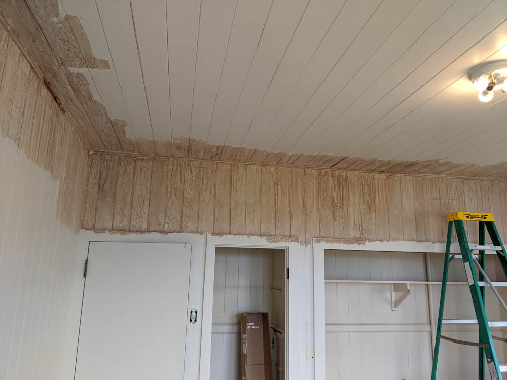
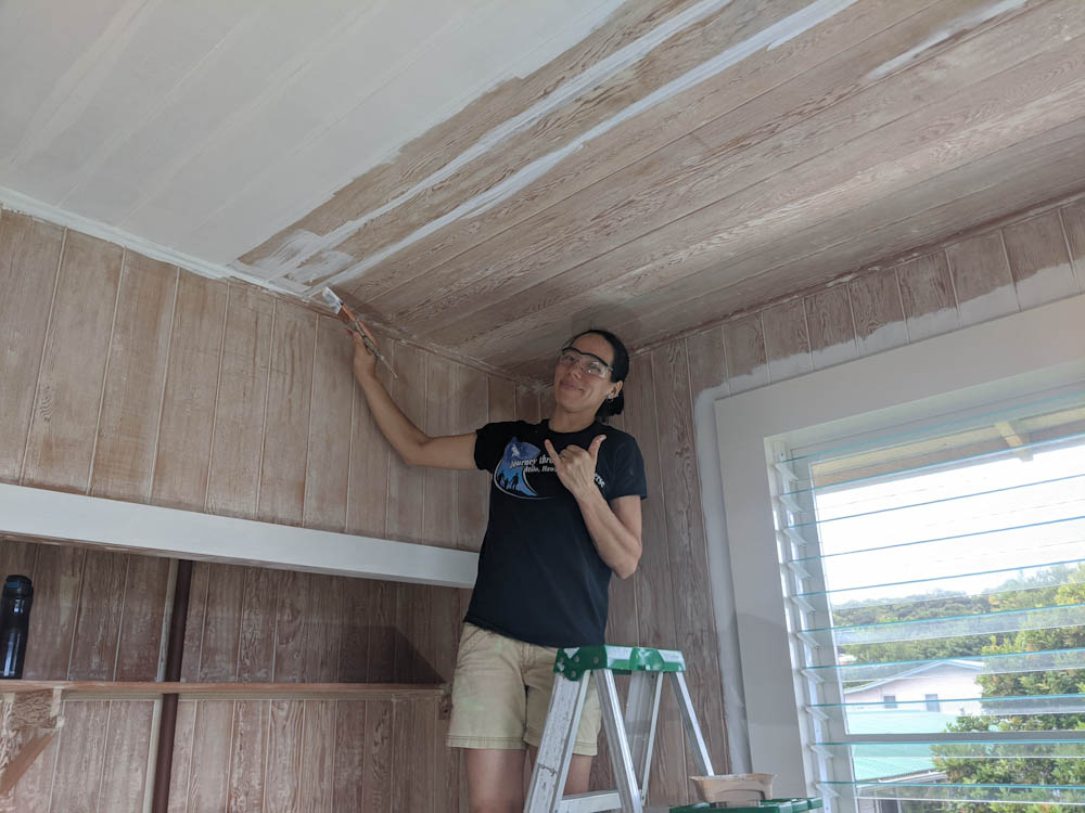
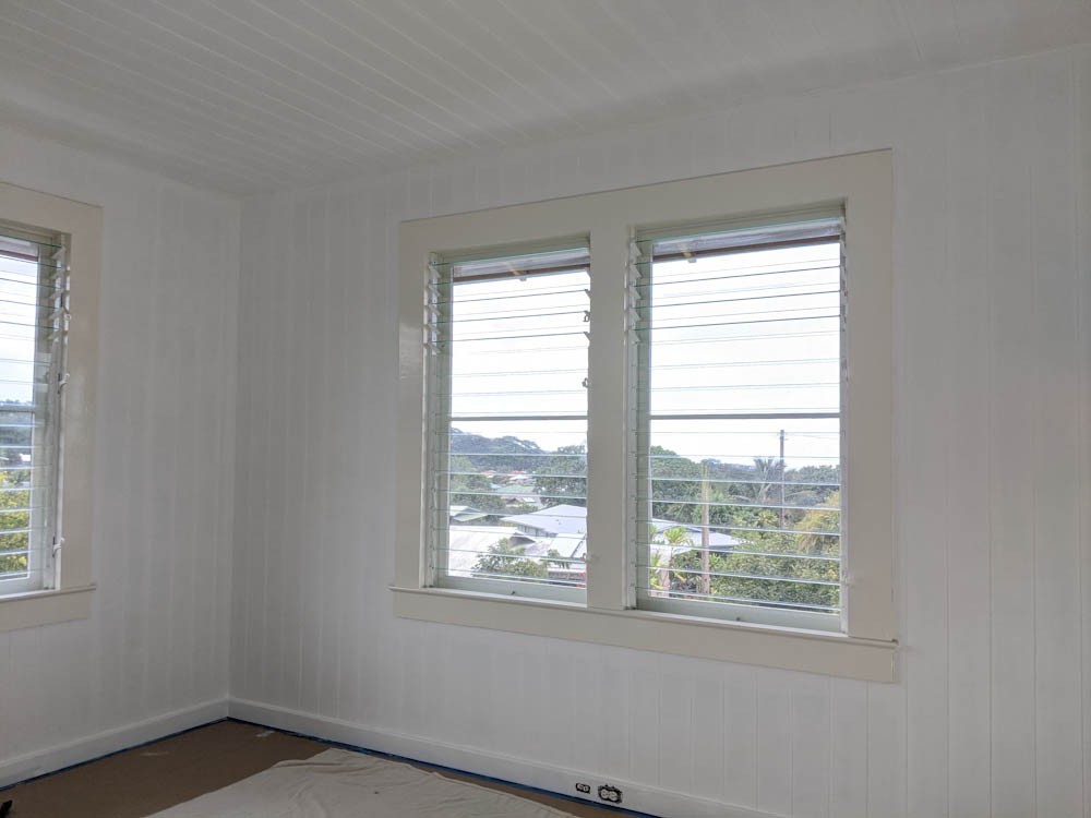
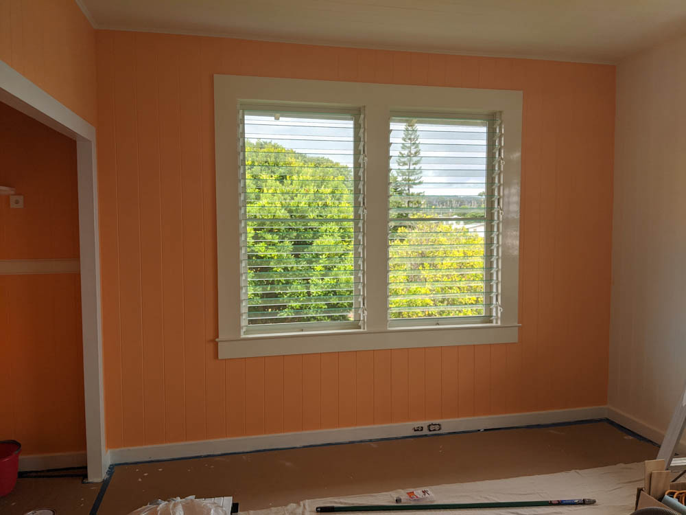
Progress on the filament dryer was stalled over the summer since all free time went into the repainting of the room. The next thing to do on the box itself was to figure out a way to mount the internal circulation fan, figure out how to run the wires, and assemble the panels into a box.
I’ve been putting off assembling the box since it’s sort of the “point of no return” in case something goes wrong, and I wanted to make sure I knew how to run the wires since it’s easier to make pass-throughs through the foam boards before they’re assembled.
In the end, however, I decided that I should just make the fan mount and affix it to the inside of the box top, and then put everything together to get the project moving again.
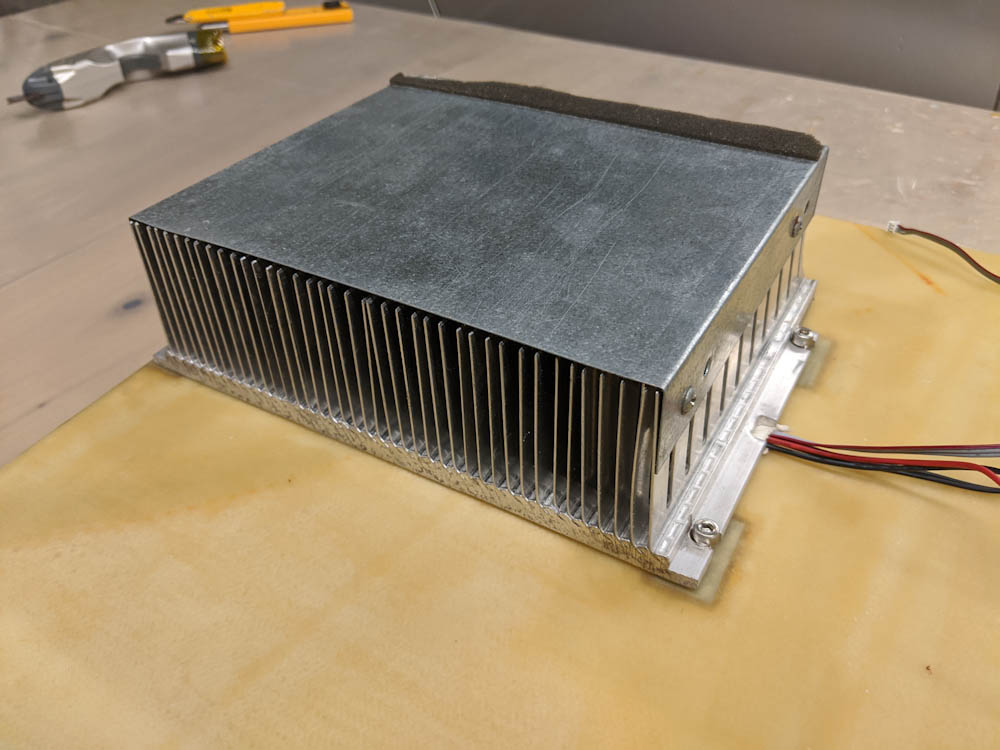
The circulation fan is an 80x25mm fan that will be mounted vertically to the ceiling of the box, blowing air down to set up an airflow inside the box. To not obstruct the filament rolls, it has to fit fairly tightly against the ceiling, which isn’t optimal for airflow since the fan has to suck the air in somewhere.
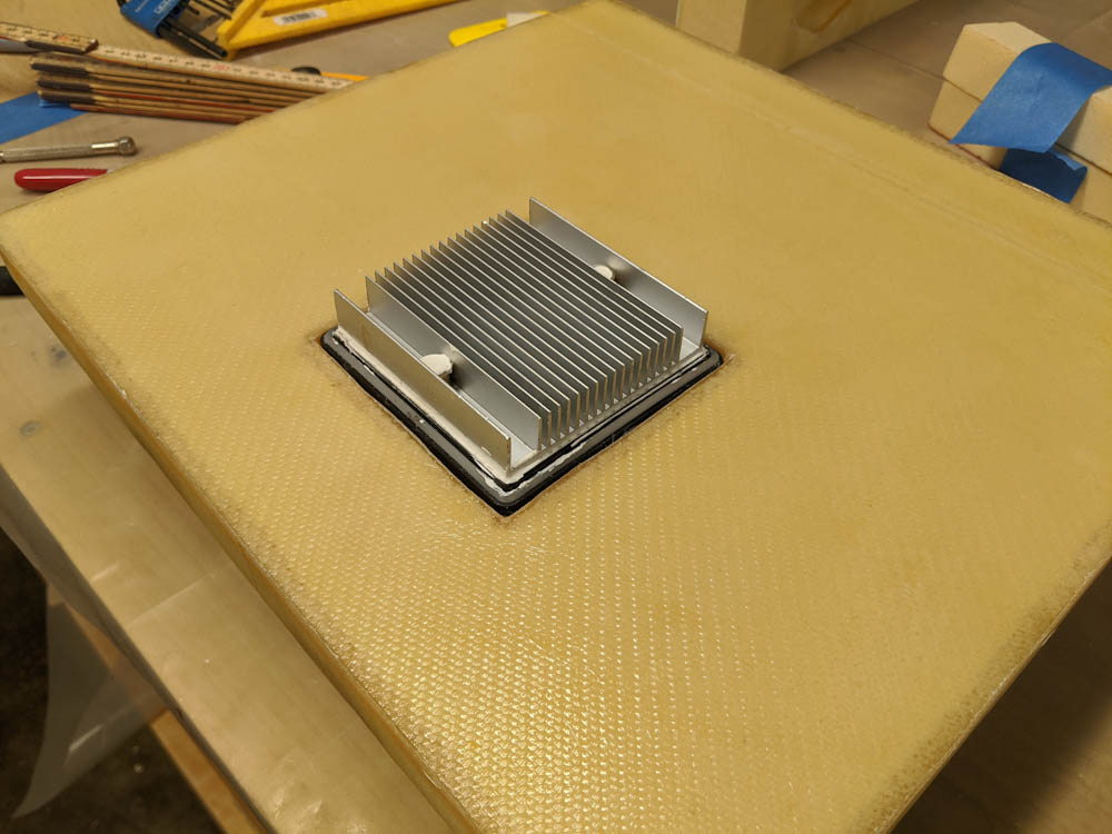
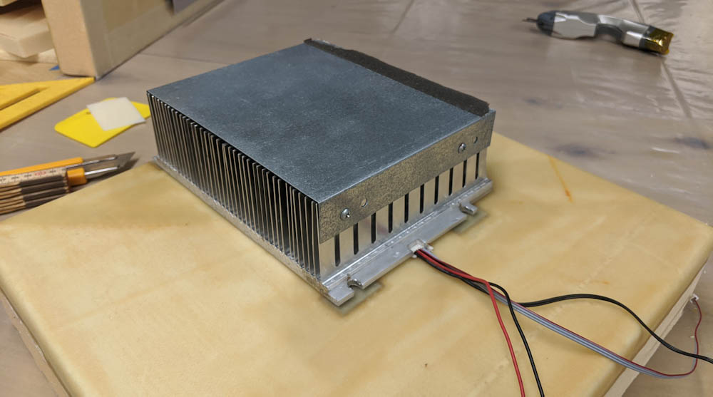
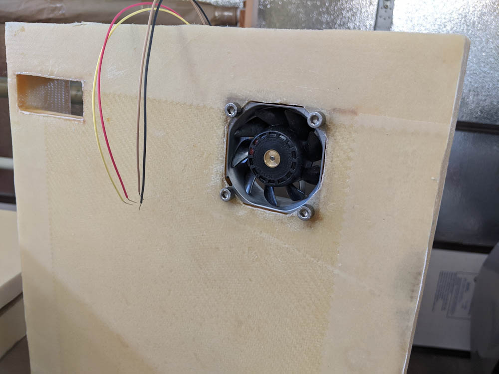
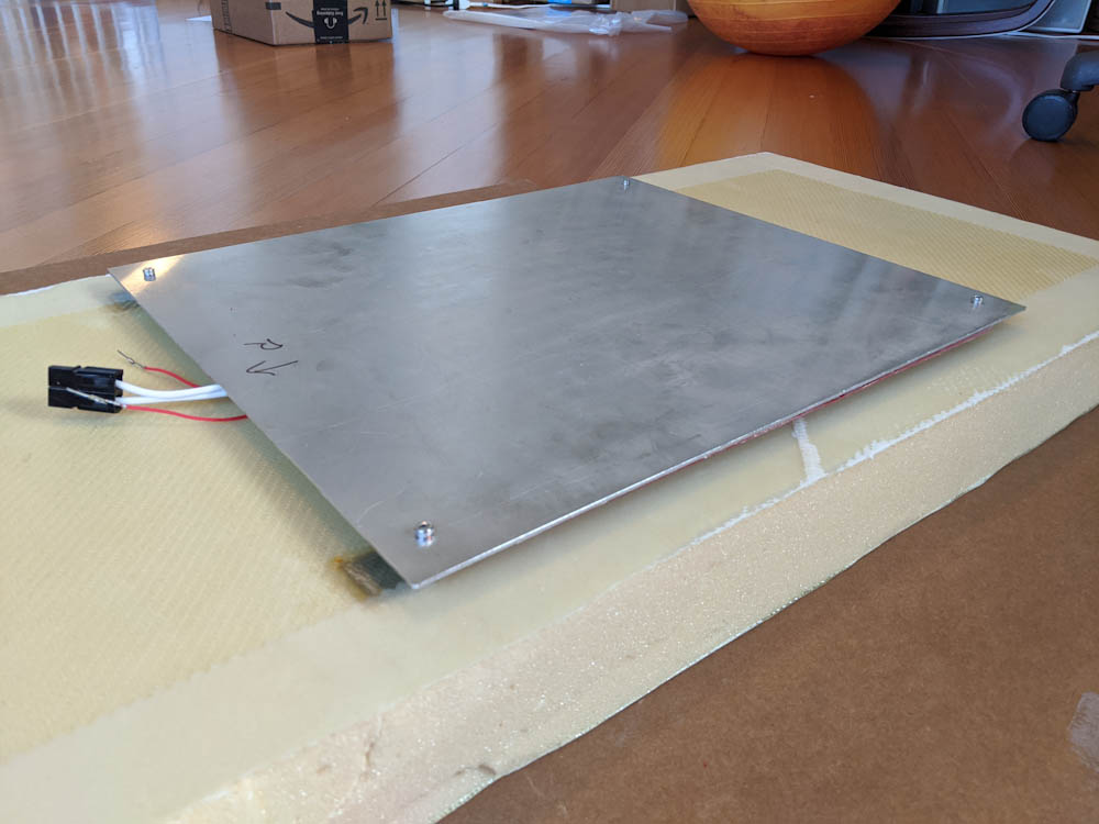
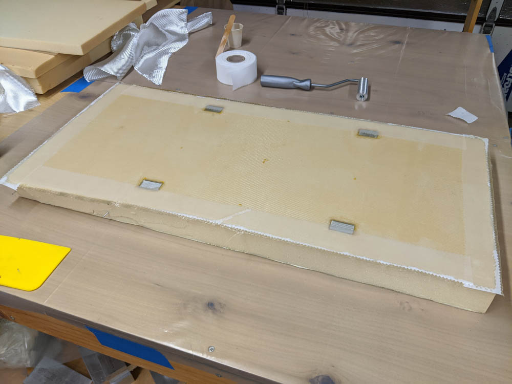
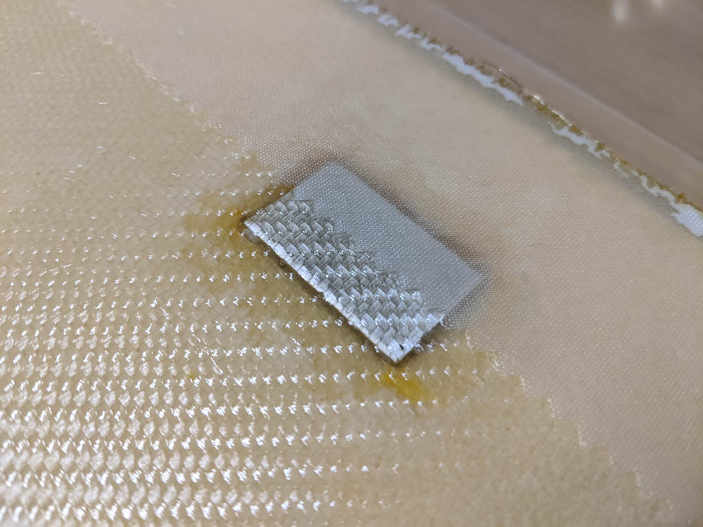
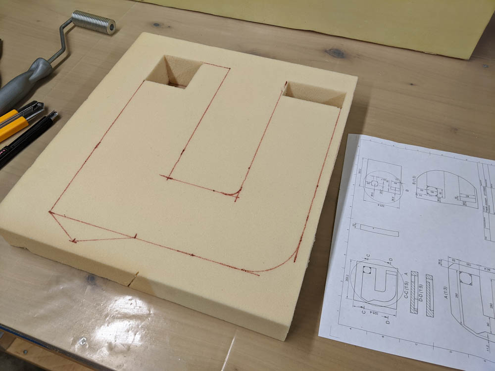
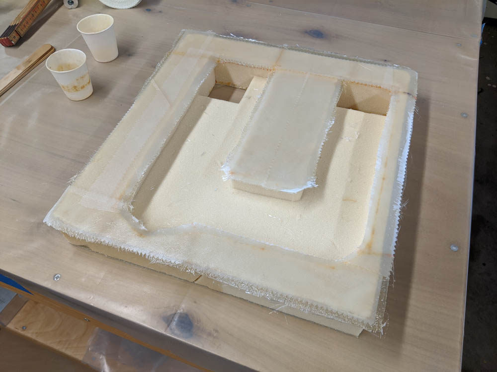
To mount the fan, I made a square bracket by laying glass on top of a 1″ thick 90x90mm large foam piece, folding it down along the sides and then out at the bottom to make feet. By cutting out a big circle in the “top”, and then cutting most of the sides away, the fan can suck air in through the slits on the sides. The airflow area is a bit smaller that I would like, and the fan definitely has a slightly choked sound when tested, at least at full speed. However, I don’t anticipate it needing to run very fast at all since all it needs to accomplish is to make sure all the hot air doesn’t stay at the top, so I think it’ll be fine.
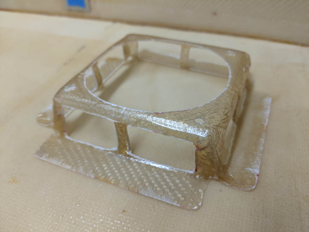
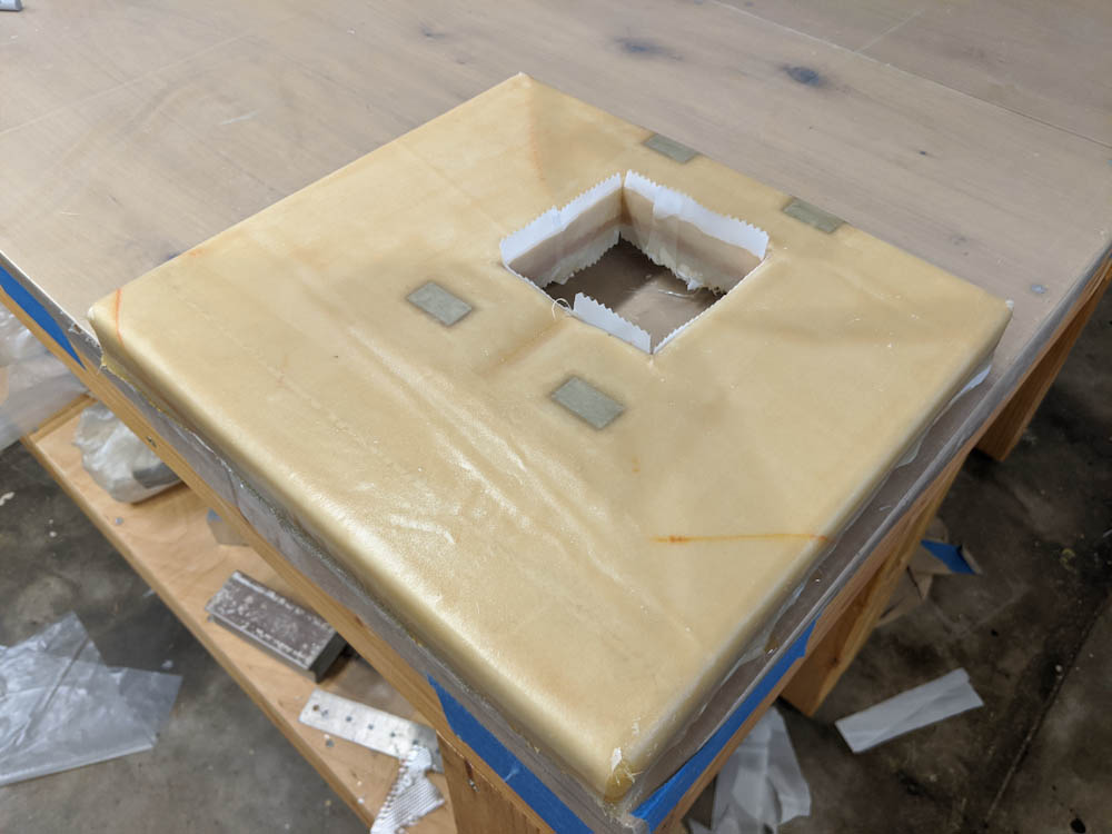
This is the bracket that will hold the 80mm circulation fan.
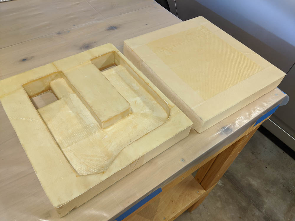
With the fan mount done, I started assembling the box. After some test fitting, tedious removal of all the peel ply, and trimming some edges that weren’t quite straight, I went for it. For starters, I assembled the left and right sides, the back, and the bottom. This is easy to do on the table, and adding the top can then be done by flipping the box upside down and adding the top in the same way.
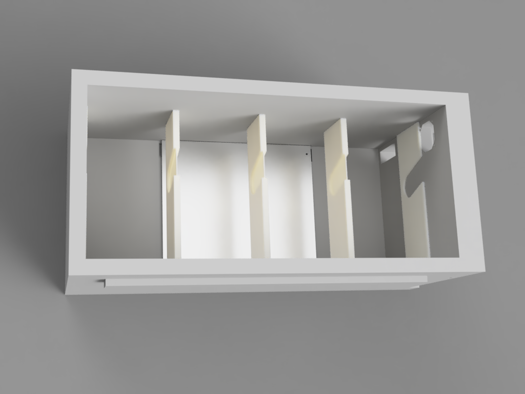
Eventually all the inner corners will get glass tape to hold them together, but to avoid disturbing the shape when doing that I started by adding flox to the foam edges and moving then against each other to “glue” the joints together. Checking that everything was square, they were temporarily fixed in place with a few large nails through the sides.
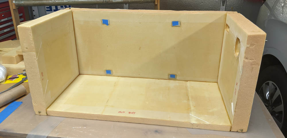
The box with the cured flox but no corner tapes yet. The top of the box won’t be mounted until the corner tapes are done, since it will be much harder to access the inside at that point.
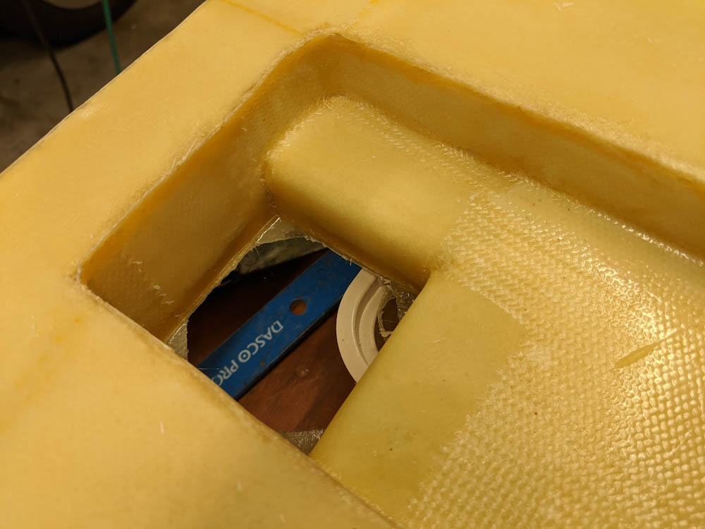
This worked pretty well. It was a little hard to fit the pieces with the flox in the joints since I’d deliberately made the flox quite dry so it wouldn’t run out of the joint, and I ended up getting little gaps in places where the flox had’t conformed. That’s not really a big deal, though, since the real strength of the joints come from the glass tapes. I can also backfill the holes in the joints from the outside before glassing that.