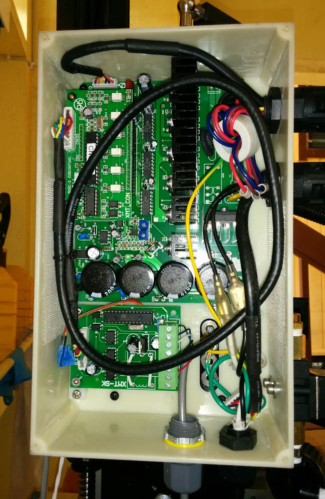
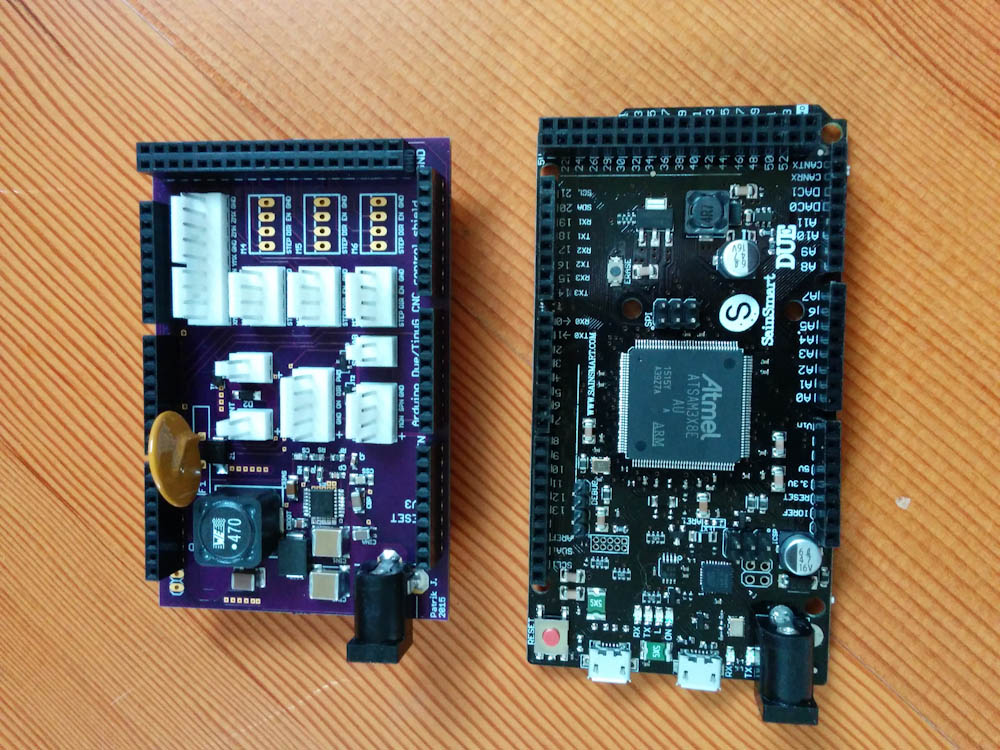
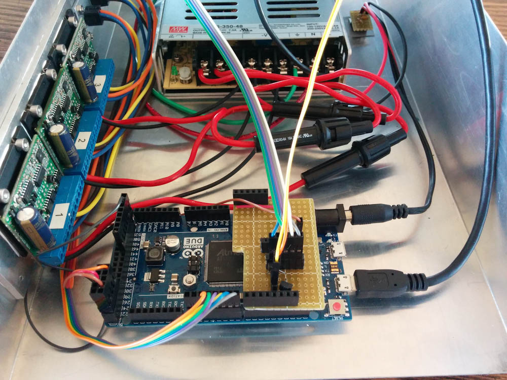
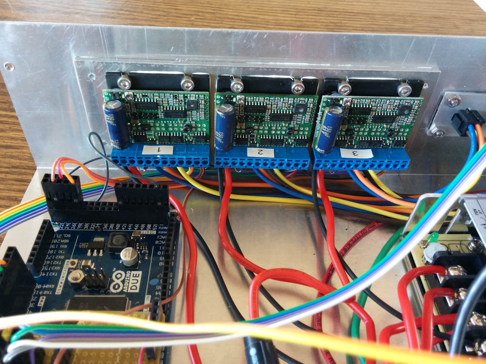
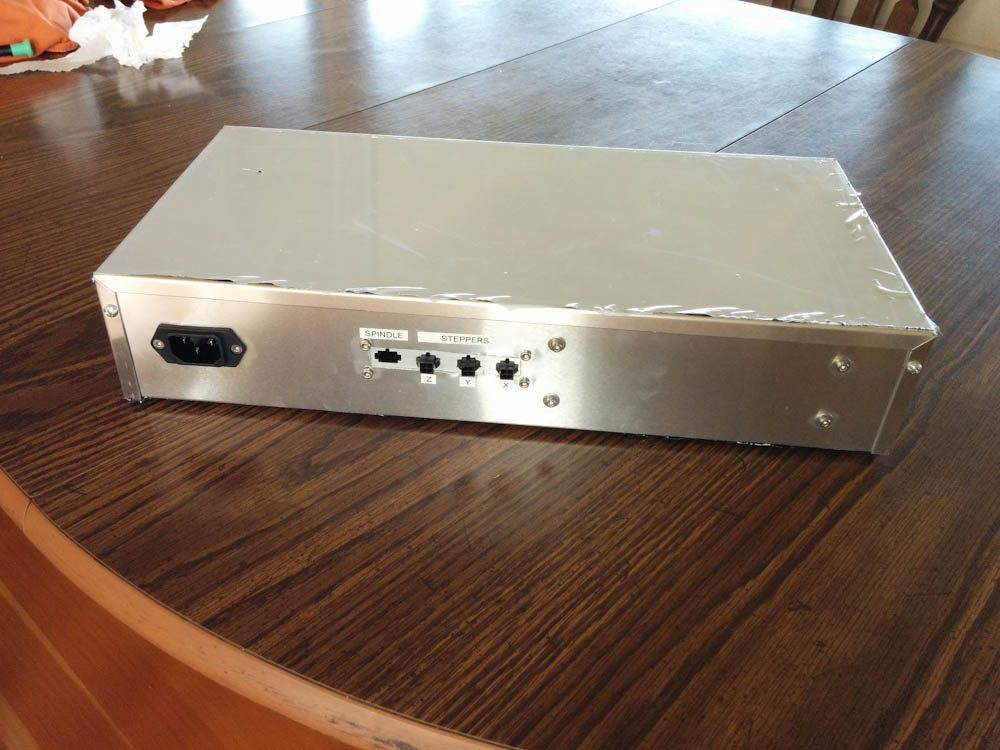
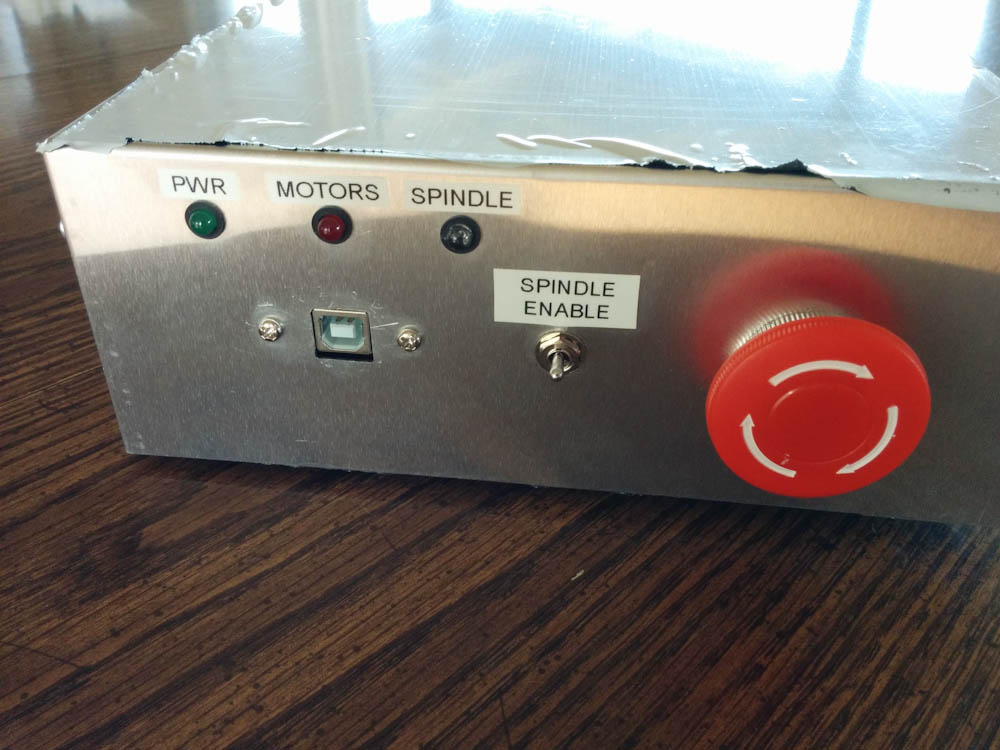
In the previous posts I described the electronics box and motion controller. (Newsflash: The Arduino Due survived! There was only a shorted input capacitor. When I removed that, it worked again, and I so far haven’t found anything that’s really broken. Amazing, dodged another bullet there.)
This post will focus on the physical mill setup. There were a few things I wanted to add, like limit switches and add a rubber chip guard for the Z-axis way and ball screw, and some things that needed checking, like tramming the column and measuring backlash. There were a couple of instances where the ball nuts contacted the table, so that needed to be fixed. And then of course figuring out what the rather severe wobble in the X-axis ballscrew shown in the video in the first post comes from.
So, in no particular order:
Tramming the column
Tramming is the adjustment of the mill Z-axis to be normal to the table, so the Z-axis motion and the axis of the spindle is perpendicular to the X-Y motion. You measure this offset by putting a dial indicator in the spindle, offset radially from the spindle axis, and then checking that the measurement in one direction and in the opposite direction are the same. Any “lean” to the spindle will show up as a difference here, and then you adjust the column until the readings are the same (and you do this in both axes). The column is bolted onto the base, so the way to adjust it is by adding shims around the bolts.
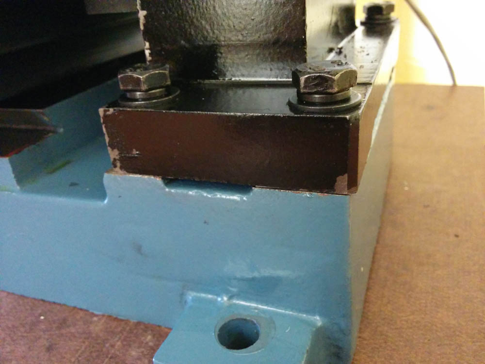
This is where the column mounts to the base. By adding shims to the four points where it is bolted in, it can be adjusted to be perpendicular.
I had noticed when taking the column off before that it did not contact the base at all 4 points, but wiggled ever so slightly when the bolts were loosened. The space, measured with a blade gauge, was about 0.025mm, not much but noticeable. Initial measurements of the deviation from perpendicular was quite severe, at 0.6mm over about 300mm in the X-direction and 0.16mm over 150mm in the Y. After calculating the proper shim thickness that would take this tilt out (and make all 4 bolt points touch at the same time), I cut them out of the steel shim stock I got from Amazon and put them around the bolts.
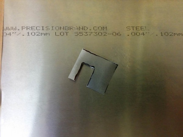
This is one of the shims, this one 0.1mm thick. The slot is so it can go in around the bolt and support it on both sides.
After tightening the bolts back, the difference was much smaller, 0.015mm/dm in X and 0.025mm/dm in Y. This is less than a hundredth of a degree in angle, and it’s also less than the amount the colum flexes when I push and pull on it, so it seems kind of pointless to try to do better.
Another thing I learned by running the table back and forth with the dial indicator still mounted was that the table is slightly bowed, the center is about 0.05-0.1mm higher in the middle than at the ends (depending on which direction you measure.)
Backlash
Backlash is the amount of play in the mechanism that leads to “lost motion” when you change direction. If you go in the same direction, you don’t notice this because it’s always to the same side. This means that if you command the table to move by 1mm in the same direction you moved previously, it will move very close to 1mm. If you now try to go back by 1mm, though, you don’t quite get back to where you started, because the play in the mechanism is now to the other side. This makes the position of the mill slightly dependent on how you got there, which affects the precision of your cuts.
The backlash mostly comes from play in the ball nuts and in the thrust bearings that hold the ball screws. When ordering the ball screws, there’s an option to have them be loaded with as-large balls as possible, which takes up most of the play. I ordered this option. To really get to zero backlash, you need preloaded ballnuts (which basically consists of two ballnuts that are locked together but such that they push in opposite directions. These ballnuts are a lot more expensive than the regular ones, so that seemed a bit excessive.
I believe the play in the thrust bearings is negligible compared to the ball nuts, because all bearings have two races that are preloaded against each other. If adjusted correctly, this should eliminate all the play.
Anyway, measuring this by running the axes back and forth, I concluded that my backlash is 0.02mm in the X, 0.05mm in the Y, and 0.06mm in the Z-axis. This is indeed less than the standard ball nuts are specified for, so I’m willing to believe that CNCFusion didn’t shaft me and indeed did match the ball sizes in the nuts. I guess we’ll see going forward if this is small enough to not affect the quality of the cuts.
X-axis ballscrew
I took the table off to see if I could trace the source of the wobble in the X-axis ballscrew, and the first thing I discovered was that the ball nut had been contacting the bottom of the table. To solve this, I just took out the Dremel and ground a small relief in the bottom of the table.

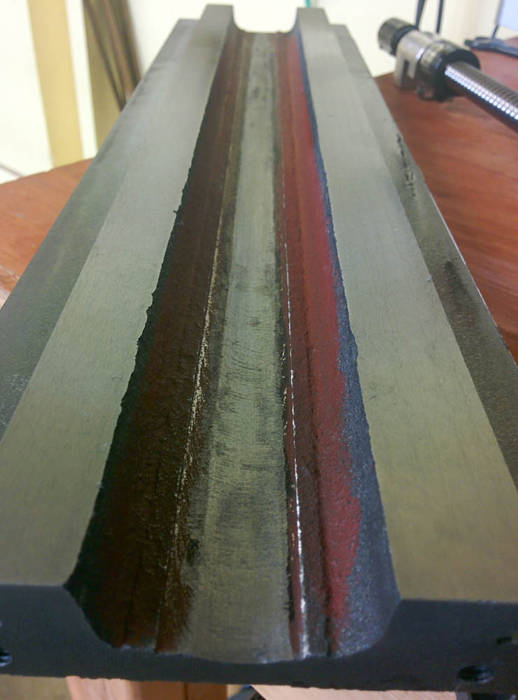
The X-axis ball nut had been contacting the table, so I gave it some more space by grinding off a small amount of material right above where it runs.
When I mounted the ball screw in the thrust bearing to see if it would wobble or if the ball nut contacted the table, I noticed that there’s something fishy going on with the CNCFusion parts. I mounted the ball screw in the thrust bearing (which is a stock mini mill part) and aligned it so it didn’t wobble when turned. Then I added shims to the thrust bearing mounting plate so the ballscrew was aligned with the center of the table. However, after doing this it didn’t align at all with the mounting plate for the stepper motor on the other end of the table.

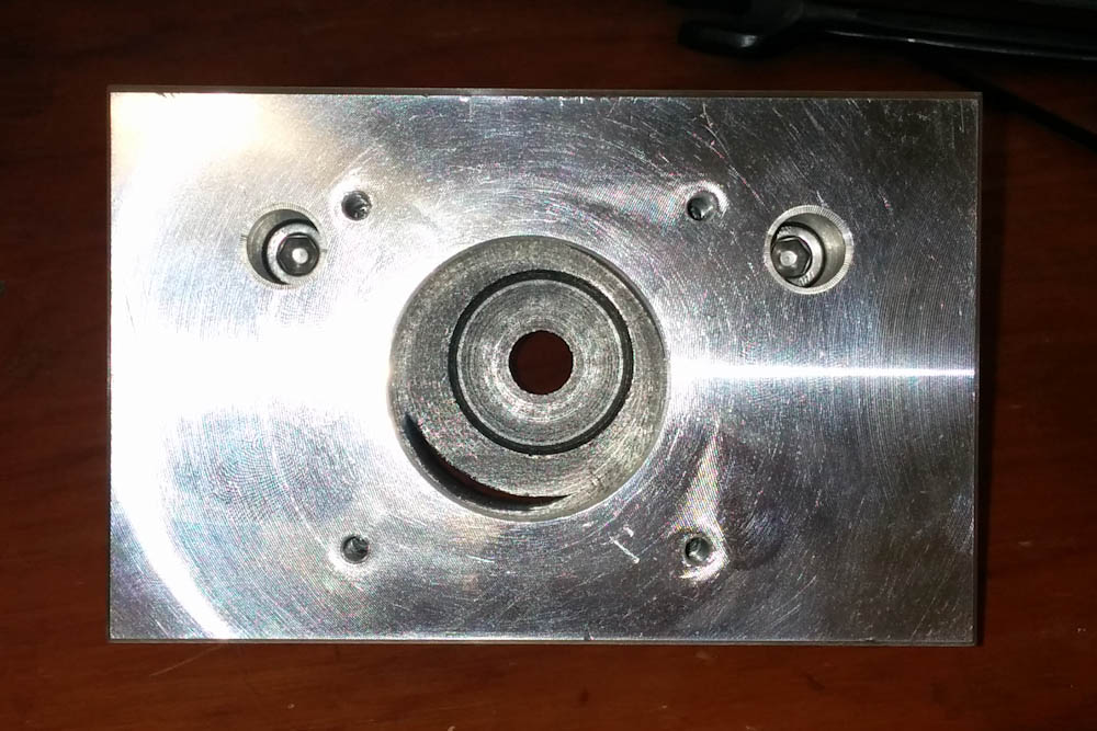
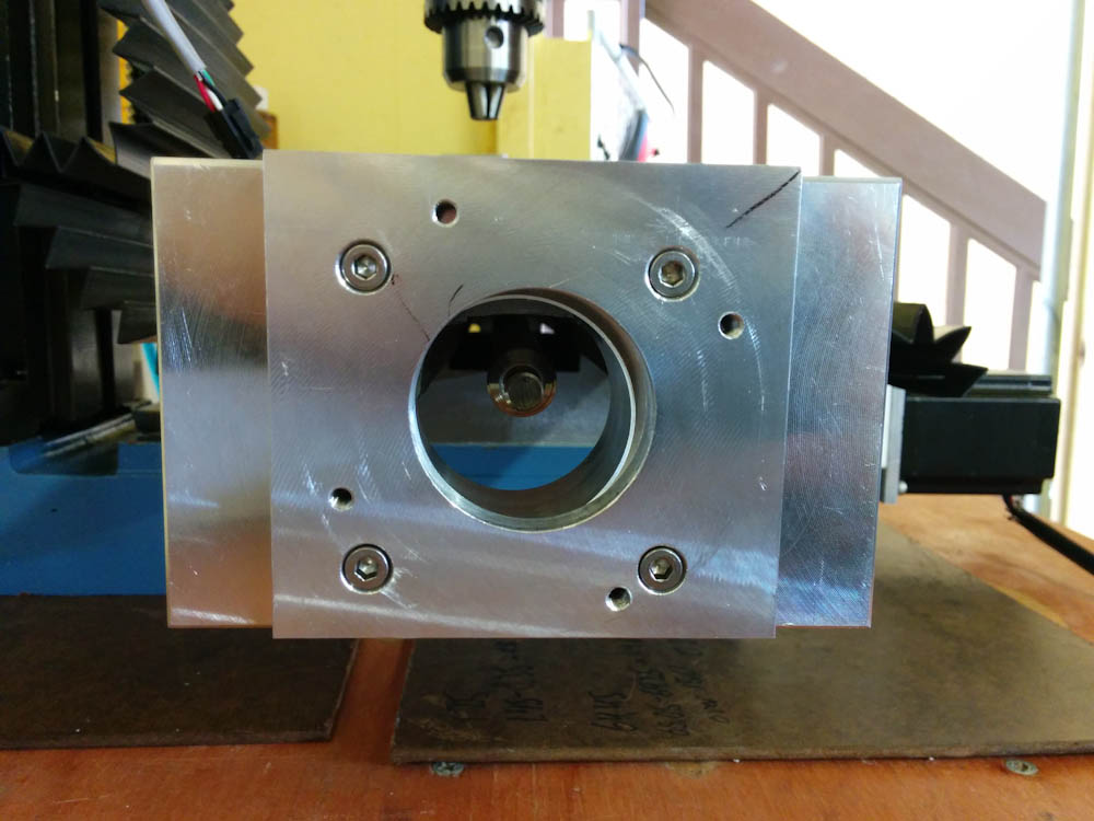
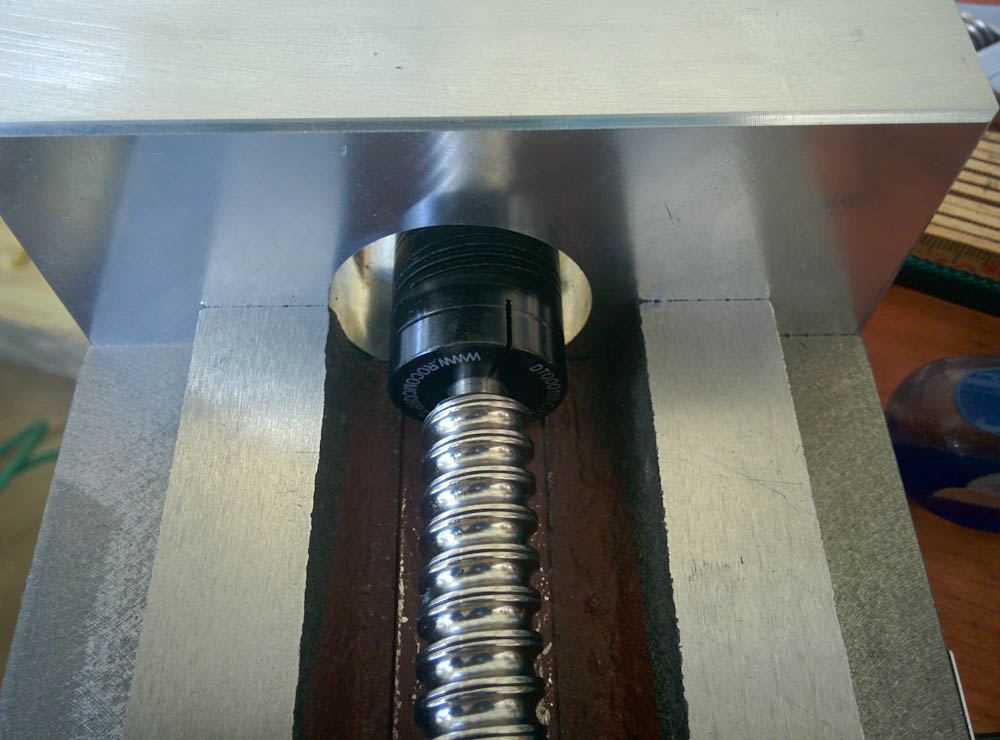
Here the ball screw is aligned, to the very best of my ability, with the axis of the thrust bearing (on the opposite side of the ball screw shown here). This also makes the ball screw go very closely down the center of the table. However, the hole for the stepper motor in the mounting plate on this side is plainly not lined up with the ball screw.
The offset is large, about 5mm laterally, and the motor mount also appears to be slightly offset in height with the axis of the thrust bearing.

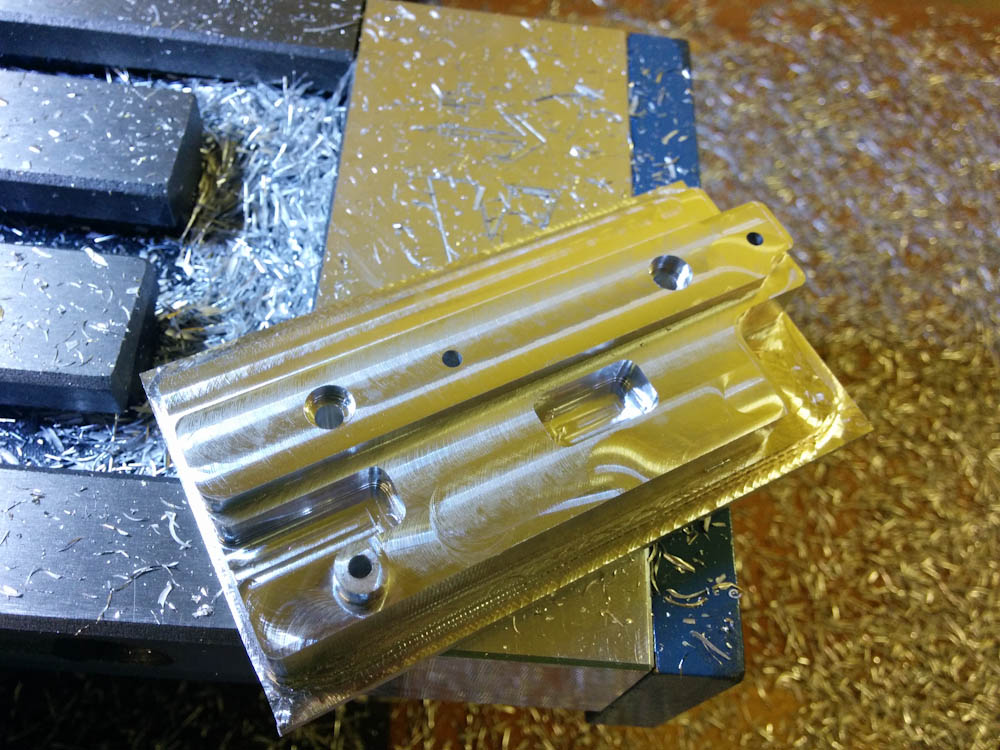
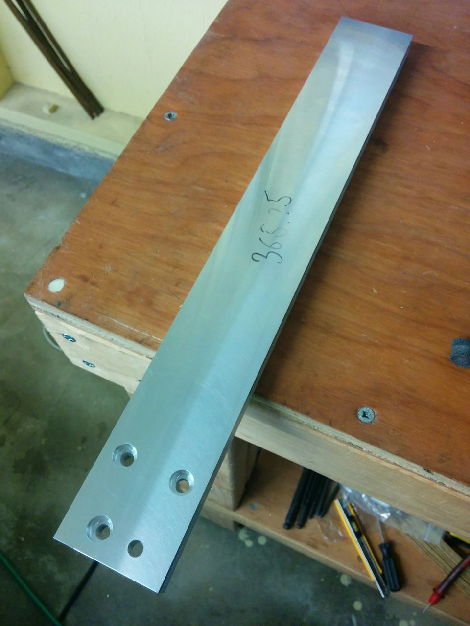
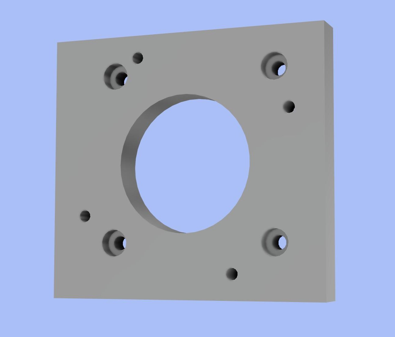
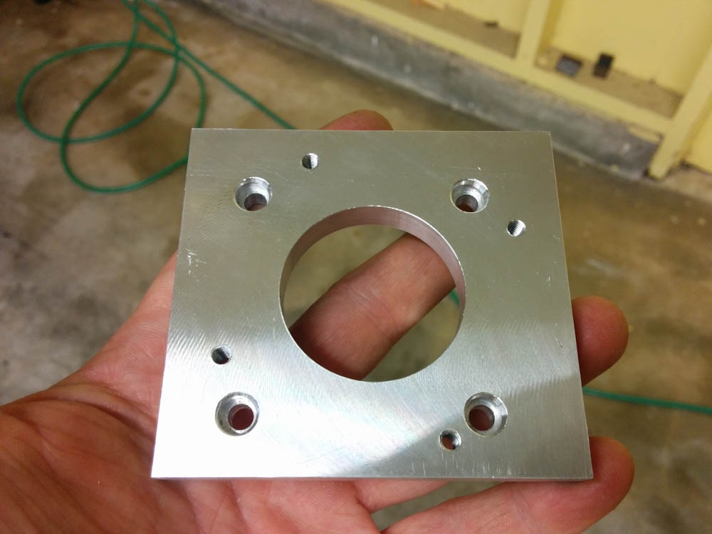
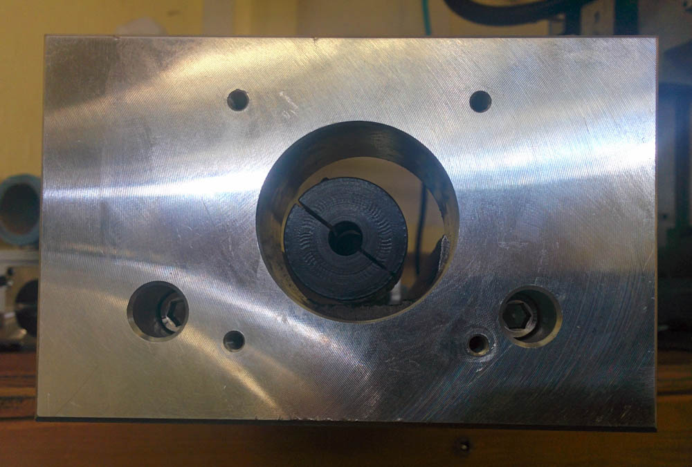
This is the stepper motor mounting plate from the CNCFusion kit. It’s obvious that the hole for the stepper motor isn’t in lined up with the center of the holes for the two M6 bolts that mount this plate to the table, but is offset to the side.
This appears to be a design error in the CNCFusion part, because the offset between the hole for the motor and the midpoint between the two M6 bolts is also visible in the pictures of the kit on the CNCFUsion web page.
This is disappointing, but I think it can be fixed by making an adapter plate that would mount on the outside of this one and offset the motor mount “back” to where it should be. The ball screw is long enough that adding a 1/4″ plate shouldn’t be an issue. I haven’t heard back from CNCFusion whether they agree that this is a mistake or not yet.
This actually explains the X-axis wobble, though. When I mounted the ball screw initially, I didn’t tighten the thrust bearing down until I had mounted the motor. Since this makes the entire ball screw “cocked” in the bearing, it will then wobble when turned. After realizing this, I tightened the thrust bearing first and then mounted the motor. This still pulls a bend in the ball screw, but it did eliminate most of the wobble. (However, the bend still means that it will bind when the ball nut is tightened to the saddle and the table run back and forth, so the real solution is to correct the motor position.)
Chip guards
The mill comes with two rubber flaps that cover the Y-axis ways and ball screws. There is nothing protecting the Z-axis from chips though, and when chips stuck on the ball screw get ingested by the ball nuts as they run over them, the bearing won’t move smoothly any more. If the chip is big enough, it can lock up completely, and it certainly won’t be good for the lifetime of the ballnuts either. Adding a chip guard seemed prudent.
Littlemachineshop.com sells extra rubber flaps, so I ordered one of those and mounted it between the bottom of the column and the spindle. I had to use some aluminum angles I had left over from the storage project to get it to fit properly, but the Z-axis is now almost completely protected.
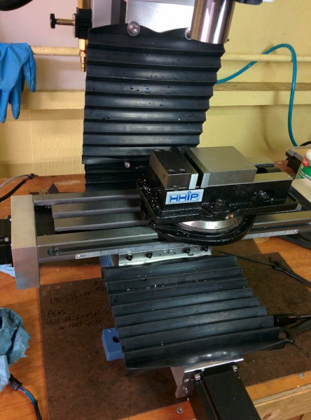
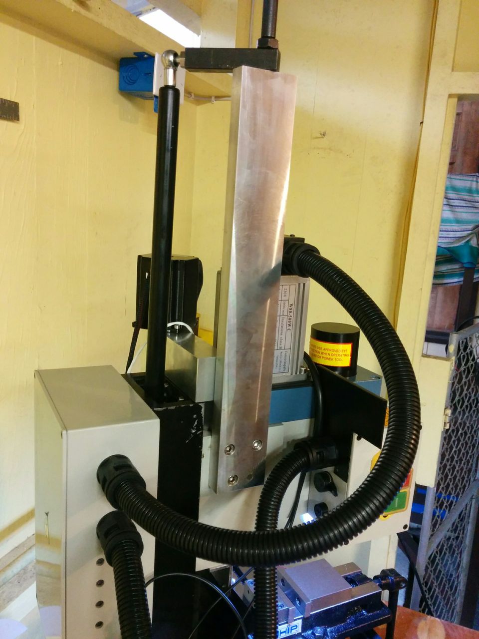
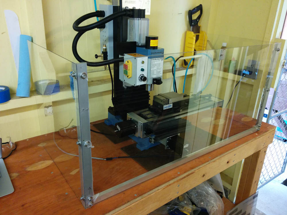
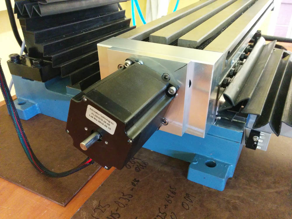
The machine with the added Z-axis chip guard and improved attachment of the Y-axis ones.
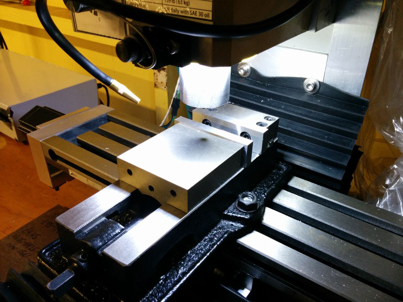
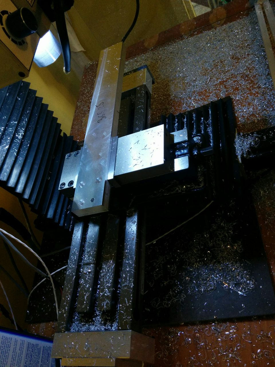
The front Y-axis guard required a small revision of its mount, because it would bunch up and get stuck between the front of the table and the Y-axis stepper motor mounting plate. To fix this I used the mill for the first time (in “1D” mode since the Y-axis was disabled) and milled a large chamfer in the motor mount plate so the rubber flaps wouldn’t get stuck as easily.
The “1D milling” down of the Y-axis motor mounting plate. Since I could do this by just running an endmill back and forth, I just locked the Y-axis gibs in place and typed G-code manually to run the table back and forth. A bit primitive, but it worked.
With the sharp corner removed and a slightly improved mounting arrangement, all rubber flaps now move smoothly and do not limit the range of motion of the machine.
Limit switches
Something that’s not entirely required but helpful is to have limit switches on each of the axes so the machine can establish where it is at boot. This isn’t really a requirement for using it, since you’ll normally line up the work coordinate system with the stock piece anyway, but the homing switches define the machine “absolute” coordinate system that TinyG uses for deciding whether a commanded move will run the axis into the end stops and stopping the move before the mechanical limits. Since I’ve accidentally run into the end stops several times already by mistyping G-code, this seems like a prudent thing to have.
Figuring out where to put the switches takes some thought. You want them to be located such that they’re out of the way, are attached to a fixed point on the machine (this avoids needing to deal with cable motion when moving), are somewhat adjustable, and only depend on the motion of a single axis. The Y and Z axes are pretty easy, since they move against a fixed part of the machine.

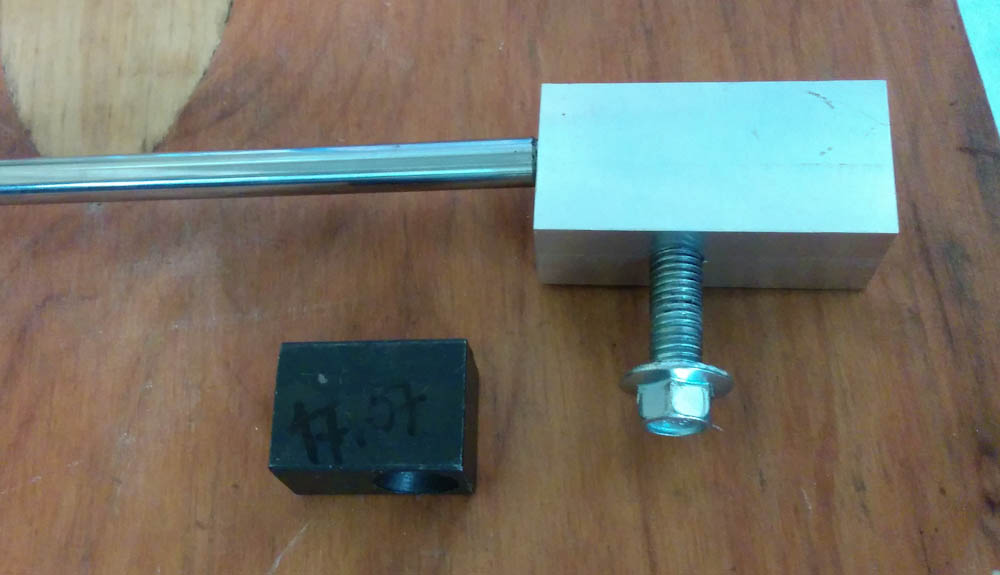
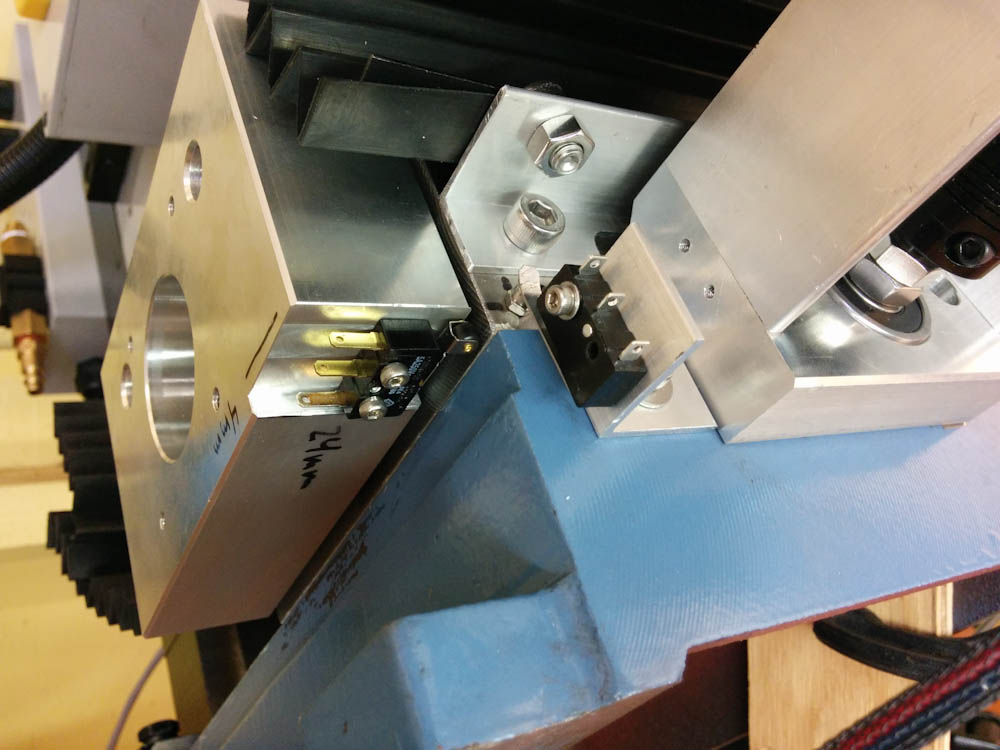
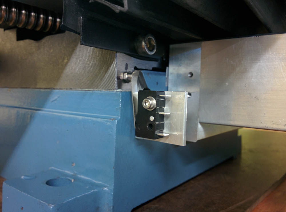
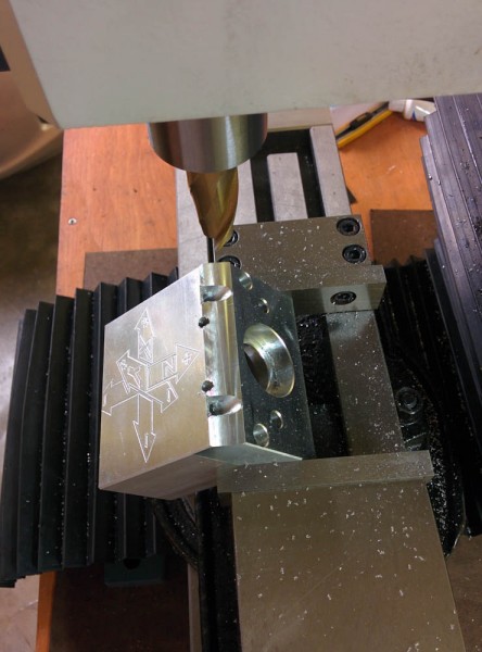
The Y-axis homing switch contacts the head of an Allen screw threaded into the saddle.
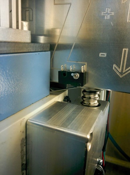
The Z-axis switch contacts the top of the head when it’s in the highest position.
I haven’t mounted the X-axis switch yet. I think I know where to put it, but until I get the X-axis motor mount fixed the table won’t move all the way in that direction because the coupler that mounts the stepper motor shaft to the ballscrew (the black, cylindrical piece at the end of the ballscrew in the pictures of the X-axis above) runs into the saddle. Once it’s all wired up and operational I’ll revisit this topic.
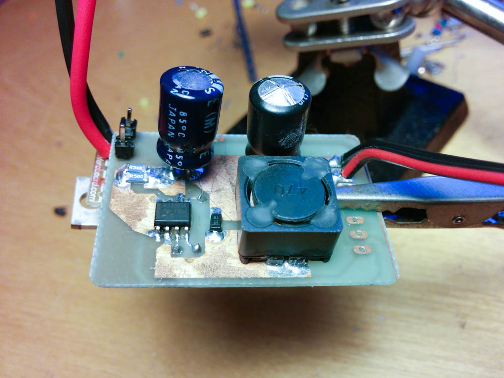
So that’s it for now, a bunch of small little things that hopefully will make the mill more usable and useful. I’m still waiting on the circuit board I designed for the 12V regulator/Arduino shield, that will probably be the next post.