As I mentioned in the last post, one of the things I wanted to make was an improved bracket for the air spring that takes some of the weight of the spindle. The stock bracket is a ~300mm long, 10mm diameter steel rod, mounted with two M6 screws on the side of the spindle, threaded into another steel rod at 90 degree angle at the top. This is attached to the top of the air spring, which is the damped kind typically used for trunk lids on cars. The force of the spring and its damper when the Z-axis moved up and down is substantial, so this assembly flexes back and forth and has already been permanently bent. I figured it would be simple to make a beefier one out of a piece of 6061 bar.
This was the first machining project that would use the CNC-controlled coolant and spindle, so the first thing I discovered was that the spindle RPM control worked fine until I turned the stepper motors on. Then the spindle started erratically speeding up and slowing down. The oscilloscope showed substantial noise on the PWM signal from the TinyG when the motors were powered, so I figured this was the same problem I had with the limit switches. A low-pass filter was needed.
Luckily I had de-soldered a resistor from the input voltage divider on the CNC control board, so all I had to do was add a 0.5uF capacitor on that pad. In combination with the in-line 1k resistor that was already there, this would make a low-pass filter with a 1us time constant. That’s about equal to a single timer tick on the Atmega8A that’s measuring the PWM signal, so that should not give appreciable distortion to the pulse widths.
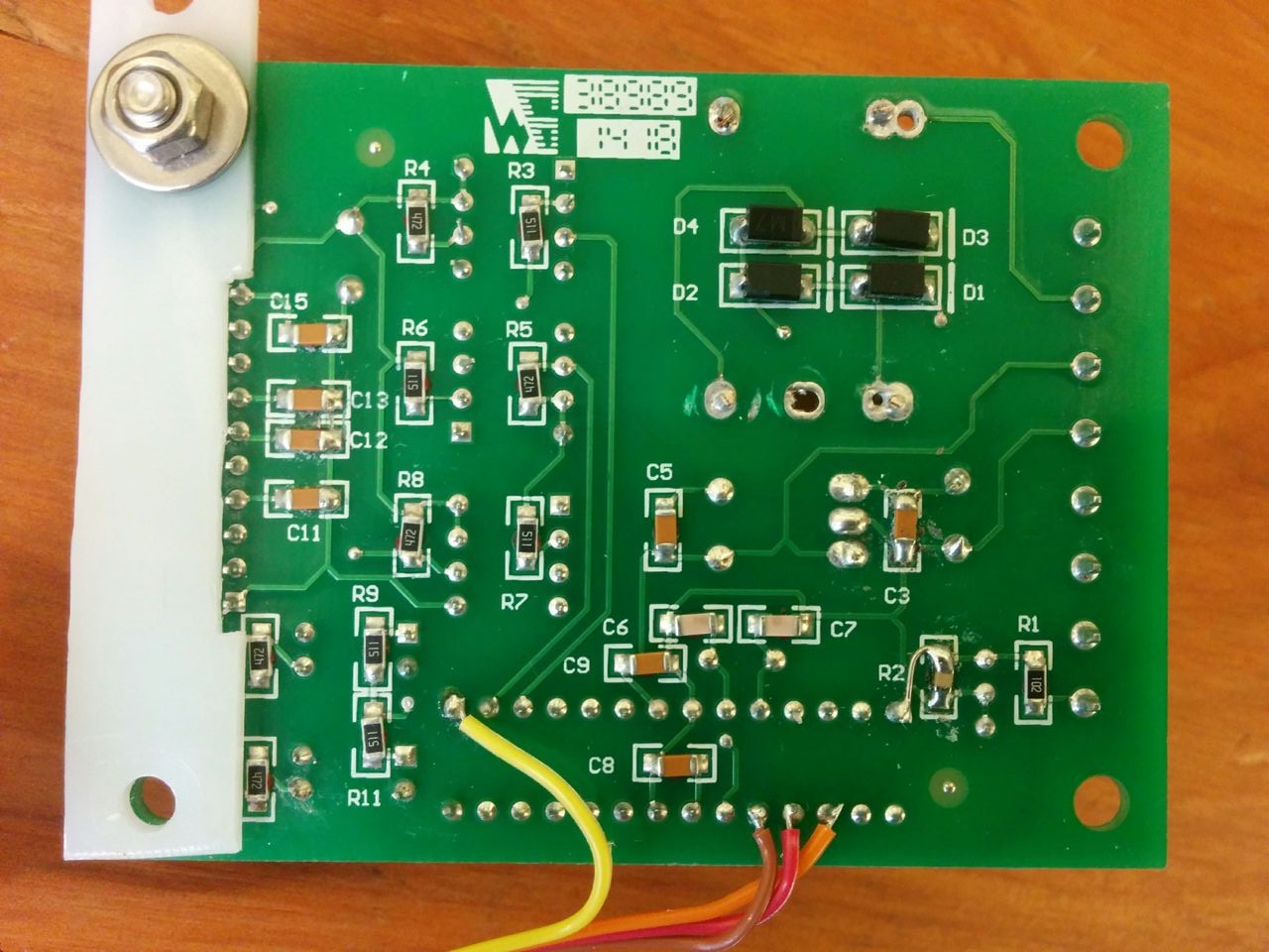
The back side of the spindle control board. The capacitor added to make the low-pass filter is marked “R2”, right next to the jumper that connects the incoming PWM signal to the input capture pin.
With the capacitor added, the RPM control now works fine even when the motors are powered. Time to proceed with the bracket.
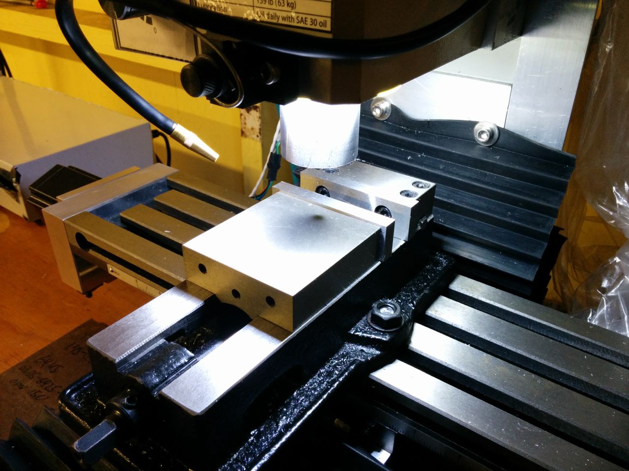
I had some trouble getting Fusion360 to do what I want when it came to the CAM setup. I was going to make it out of a 2″ x 0.75″ bar, and it needs to be about 360mm long. The biggest issue was that this is more than the maximum travel on the mill, so I had to figure out how to split the tool paths. As you will see, it’s a pretty simple part, though, so once I figured out how to do it, it wasn’t a big deal. It just means you have to reposition the part and re-set the zeropoint numerous times, which makes it more cumbersome.
Since the last post, I also mounted a LED ring that I got off ebay around the spindle. It’s 80mm diameter, which fits perfectly on the little plastic cover plate around the bottom of the spindle. Unless the endmill is very short, like a miniature, 1-2mm one, they are large enough in diameter to not have the spindle cast a shadow on the endmill.
The LED ring illuminates the area around the cut very well. In this picture there is a shadow from the spindle, but the spindle would be higher up unless the endmill is tiny.
This was the first time I used my G-wizard trial to calculate feeds and speeds for the “adaptive clearing” operations in Fusion 360. This creates toolpaths that have constant engagement, which means you can be a lot more aggressive on the feedrate since you know the tool won’t go into a corner and load up. G-wizard spit out a 1mm stepover and a feedrate of 1600 mm/min for the 2mm deep cut I was making. This was by far the most aggressive cut I’ve done, but it worked great. I made a short video of the operation:
That as about the only thing that went well though. The “Spra-Kool” coolant nozzle works, but it’s a but touchy on the adjustment. It’s easy to get no coolant at all or to drench the stock. It doesn’t even seem to be fully repeatable, sometimes it worked fine only to not have any coolant at all after it’s paused for a tool change. I also fat-fingered G-code when trying to set the zeropoint and snapped off my edgefinder. It was only $7, but still. Then I accidentally started milling the wrong side for the operation that was cutting the screw holes. Luckily two of the holes are symmetric and lined up perfectly even after the stock was flipped. The third hole was offset enough that the bad hole didn’t interfere with the good one. It just looks bad. This is how you learn things…
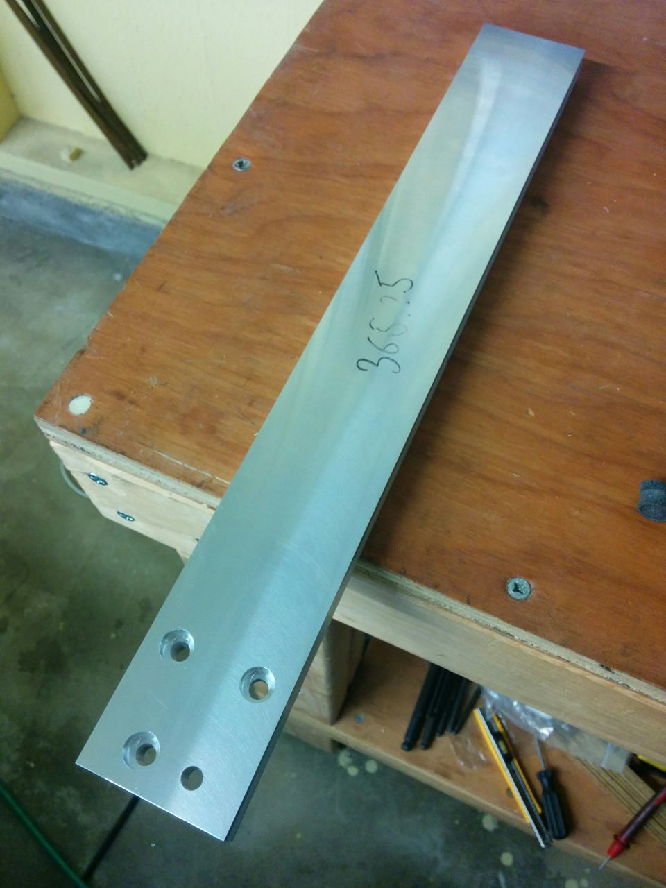
Here’s the final part. The hole without the counterbore is the one I accidentally drilled by putting the stock wrong side up.
I’m also pretty happy with how the Lexan chip shields are working out. It’s a bit of a pain to move them out of the way when working on the mill, but otherwise they do a great job of keeping the chips confined. And there were a lot of chips made here.
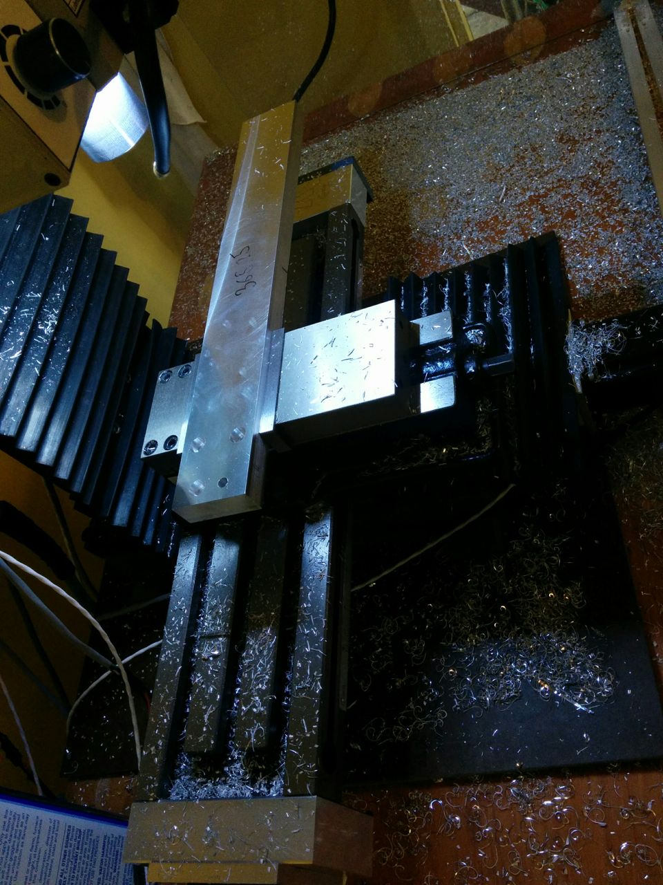
At the conclusion of the milling operation, the chip shields had held in quite a lot of chips. Without them, I’d be walking through that…
Luckily, that bracket fit perfectly. I could make it even better by making a new bottom mount for the air spring. The stock one mounts it a bit too close to the inner surface of the column so it’s not quite vertical. And I need to get an M10 bolt for the horizontal bar on top. The only thing I had that was threaded M10 was the original bracket, which works but looks pretty ridiculous since it’s 300mm long…
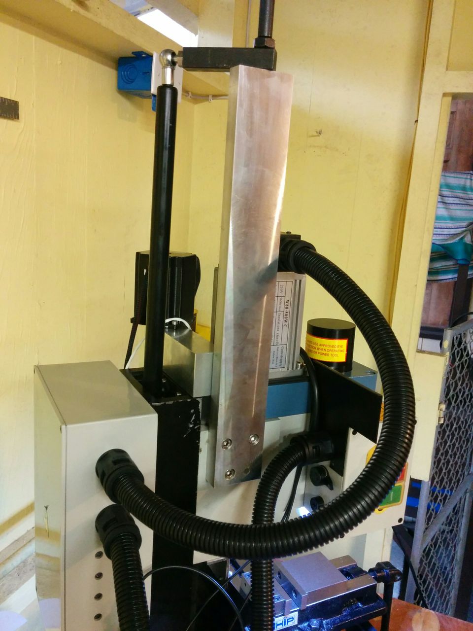
The new bracket in place. The horizontal bar at the top is now screwed in with the old bracket. I didn’t have an M10 bolt around.
So I think that’s a success, even if there were some teachable moments along the way. I think the mill is pretty much operational now.
Pingback: CNC Mini Mill #11: A little more work on the air spring – Patrik's projects