With the limit switches working, it was time to tackle the spindle control. The spindle is normally controlled with on/off switches and a speed knob on the spindle itself, but for CNC use it’s useful to have the ability to run the spindle from the G-code. I ordered a “CNC spindle control kit” with the mill, but didn’t touch it for a long time since there were more pressing things to fix.
The kit consists of a small circuit board and a PDIP28 IC that replaces the one in the motor controller. The IC turns out to be an Atmega8A, and there’s another one on the circuit board. The board is powered with 110V and has inputs for spindle on/off, direction, and speed. The instructions aren’t really clear on how the inputs are supposed to be driven, though, so the first step was to figure out how the board was wired.
It’s not a very complicated board, so there’s not that much going on. The 110V inputs go to a transformer, a full-wave rectifier, and then to an L7805 5V voltage regulator, providing 5V power.
There are 5 optocouplers on the board. Two are directly connected to the forward/reverse and on/off inputs, where sinking current will turn on the optocoupler. I looked up the datasheet for the optocouplers and the current will be about 10mA. This is too much to connect directly to an Arduino Due, but I knew this when I designed the shield so it has two MOSFETs to handle these. (There is also a third optocoupler connected to an input called “FLN” that is not described anywhere…)
The remaining two optocouplers are hooked up to the Tx/Rx lines on the Atmega8A, and the speed input to one of its AD converter pins through an adjustable voltage divider. The instructions say to adjust the pot until you get full speed, so clearly the speed input is an analog voltage. Apparently common boards like the Geckodrive G540 have an analog voltage output for this purpose, but this is not so good for hooking up to the TinyG sinc its spindle speed output is a 100Hz PWM signal with the duty cycle determined by the speed.
I could have attempted to low-pass filter the PWM signal to turn it into an analog voltage, but given how much noise there was in the limit switch lines I wasn’t convinced an analog input was the way to go. Instead, I figured I could just reprogram the Atmega8A, which is just a smaller version of the chips used in the Arduinos, to decode the PWM signal directly. Since that’s a digital signal, it’s much less susceptible to interference.
The problem was of course that this required me to reverse-engineer what the existing Atmega was sending over the serial line. By hooking the Tx line up to the oscilloscope and using the adjustable pot to shift the voltage on the input, I was hoping to figure out what it was doing.
It turns out it wasn’t that complicated. The serial protocol consists of sending a 0x55, two 8-bit numbers, and then another 8-bit number that’s the sum of the two previous ones (presumably as a checksum). The two 8-bit numbers contain a 16-bit number between 0 and 1023 (coincidentally exactly the range of the 10-bit AD converter on the Atmega), where 0 is for 0 input voltage and 1023 is for 5V.
Hence, all I would need to do was program the Atmega to decode the duty cycle of the incoming PWM signal, turn it into a 10-bit number, and then send it over the serial port. Shouldn’t be a big problem. I was not able to pull the original program off the chip, it appears to be locked, but a new Atmega8A is $3.
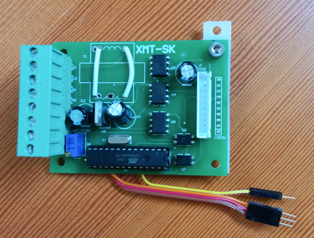
The spindle control board from Littlemachineshop.com. The transformer has been replaced with the two white jumper cables. The 4 loose wires are for hooking up the SPI connectors to the AVR programmer.
As for the 110V input, that seemed unnecessarily complicated. Since the connections to the motor electronics all go through optocouplers, there’s no need to isolate this board. Instead, I can just use the 12V from the step-down controller on the Arduino shield and send that along with the inputs to power the Atmega8A on the board. So I de-soldered the transformer and jumped it with some wires. That way I can plug either of the 110V inputs to 12V and the rectifier will handle the polarity.
Programming the Atmega8A wasn’t difficult. The code is in the bitbucket repo if anyone wants to check it out. It uses the input capture interrupts to record the value of the 16-bit timer when the input switches value. Calculating the duty cycle is then simple: at every (say) positive edge, you calculate (now – last_negative_edge)/(now – last_positive_edge). It turns out to be extremely accurate – by sending S commands to TinyG I get exactly what I expect over the serial port, to the full 10 bit resolution. The most complicated thing is how to handle duty cycles of 0 or 1, since then there are no edges to detect. This is done with the timer overflow interrupt, such that if no edges have been seen for an entire timer overflow (32ms) it will just read the value of the input as either zero or one. The timer overflow also sets a lower limit on the PWM frequency that can be used of ~31Hz. Since TinyG uses 100Hz, that’s fine.
The one bug I’ve found is that for duty cycles very close to 0 or 1, there’s not enough time to record the timer value and switch the interrupt polarity before the next edge, so it ends up missing it and wraps around to the next cycle. The only manifestation of this is that if I command a spindle speed of 2499 rpm, I get something like 1250 (because it ends up calculating a duty cycle of 50%). 2500 works fine, as does 2498. I find it hard to believe I would ever use 2499 rpm, so I’m not too bothered by this. If it turns out to be necessary, it can be avoided by limiting the duty cycles to be between something like 0.01 and 0.99 rather than 0 and 1.
I mounted the spindle control board in the box with the other spindle electronics at the back of the mill and ran a 6-part shielded wire to the stepper control box.
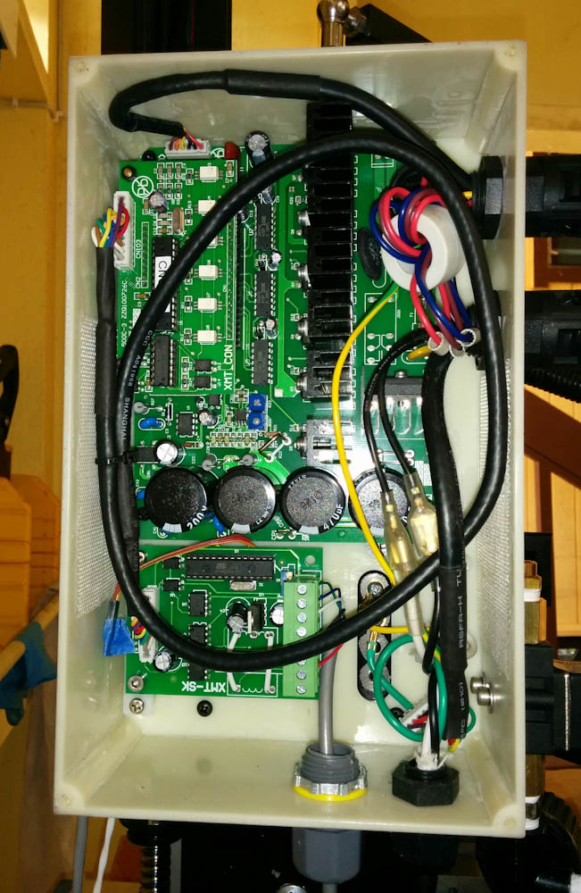
The spindle motor electronics box on the back of the mill, with the CNC spindle control board mounted in the lower left.
The setup seems to work. I can turn the spindle on and off using the M3/M5 commands in TinyG and set the spindle speed. The spindle is advertised as 100rpm, but it actually runs slower than that. It’s not very usable, though, because the motion is quite uneven at such low speeds. It’s got a lot of torque, though. If you grab the spindle with your hands, it will slow down momentarily and then you can hear the motor current ramping up and controlling back to the set speed. Then when you release, the spindle will speed up momentarily and then quickly ramp back. In any case, I limited the minimum speed to 100rpm in the TinyG settings.
One thing that doesn’t work is the forward/reverse setting. I think this is just that it’s not enabled in TinyG, but since I’m not sure why I would want to run the spindle backwards anyway I haven’t looked into it yet.
While I was at it, I finally made a wire for the coolant solenoid and hooked it up, too. That also works, so now there’s both working coolant and spindle control. Check it out:
I think that actually completes all the necessary mill setup. Wohoo! Time to make something. I want to make a better mounting bracket for the air spring, the standard one flexes all over the place, so I think that’s going to come next.
Checklist for using the spindle control board with TinyG
In case there’s anyone else out there that wants to use this spindle control board and feed it PWM from TinyG, here’s the full list of things I did:
- De-solder the transformer and add jumper wires as shown in the picture above, if you want to run it with DC rather than 110VAC.
- On the back of the board, remove the 5k resistor marked “R2”. This resistor attenuates the input signal too much.
- Solder a jumper between pin 14 on the Atmega and the pad of the resistor you just removed. (The pad connected to the adjacent 1k resistor, not the ground pad, that is.)
- Adjust the pot with 5V on the VFD input so that the voltage on the Atmega input capture pin 14 is as large as possible. It will end up being around 4V. This is sufficiently large to be reliably read as a one. (If it wasn’t, the pot would have to be desoldered too, but no point in making unnecessary damage.)
- Order a new Atmega8A from mouser.
- To program it, you’ll need something like the AVR pocket programmer. The procedure is the same as that described in the Xbee wireless bootloading How-To.
- You’ll also need a way to connect the programmer to the SPI pins, like the soldered leads in the picture.
- The spindle control board contains a 16MHz crystal, so program the fuse bits to be 0xff/0xc9 for the low and high bits, respectively.
- Clone my arduino library on bitbucket and build the “spindlecontrol” project by running make in that directory. (You’ll need a working avr-gcc environment for this to work.)
- Program the Atmega with the generated hex file using avrdude. This will be something like “avrdude -p m8 -c usbtiny -U flash:w:build-cli/spindlecontrol.hex:i”.
- If you now hook up a TTL serial receiver like Sparkfun’s FT232 breakout board to the Tx output on the Atmega you should see it sending a repeated string of 0x55 0x00 0x00 0x00 when the VFD input is disconnected and 0x55 0x03 0xff 0x02 when it’s connected to 5V. The easiest way to make the connection is with female headers to the 10-pin connector. Hook 5V to pin 10, ground to pin 1, and the Rx on the receiver to pin 9.
- Follow the instruction that came with the kit for replacing the IC on the motor board and hooking it to the spindle control board with the supplied 10-pin cable.
- Now you can hook the spindle control board to the TinyG (or any other motion controller that provides PWM output, like grbl.) Just remember that the on/off and forward/reverse inputs require sinking 10mA to turn them on. Make sure whatever you’re connecting them to can handle this.
Pingback: CNC Mini Mill #10: A better air spring bracket, and some tweaks | Patrik's projects
Hi,
I think the mysterious “FIN” pin is the RPM coming back from the motor driver, it’s just connected wrong on the controller board. When I flipped the associated optocoupler I got a fluctuating DC reading on my multimeter, which I suspect is a serial output. I haven’t gotten around to verifying that, though. If it is, you could probably reprogram the Atmega to decode it and output a pulse train or PWM to the motion controller, and get a live RPM reading. Or at least trigger an e-stop when the spindle overloads and stops…
Cheers,
Lars