One of the remaining things to hook up to the mill were the limit switches. This has taken forever, but I was waiting on some shielded 2-conductor wire I ordered on ebay. It arrived a few days before Christmas, so now it was time to check that item off the list.
I briefly talked about mounting the Y and Z switches back in part 4. The X switch was a bit more tricky and that had to wait until the X-axis ballscrew alignment issue was fixed.
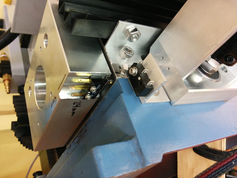
The Y-axis limit switch is on the right, mounted on a small piece of aluminum angle. An M2.5 screw on the saddle makes the trigger point adjustable. The X-axis switch on the left is a roller switch left over from the ShapeOko. I made a cutout in the X-axis motor mount so the limit switch can act against the saddle. Without this cutout, the switch would trigger against the base of the mill, where the point of contact would depend on the position of the Y axis.
In order for the X-axis switch to trigger on a consistent point, it has to touch the saddle. For this to be possible, the X-axis motor mount had to have a slot cut into it. Similarly to how I worked on the Y-axis motor mount, this was accomplished with another episode of “2D milling”, with the mill X-axis locked.
With the X-axis taken care of, all three switches were operational and ready to be wired up. The back panel on the electronics box needed to have another hole cut into it for the new connectors, and I milled the panel mount cutouts for the Micro-Fit 3.0 connectors from a design in Fusion360. This was a lot better than the ones for the stepper motors that I did manually. The cutout in the box was still done manually, and it shows…
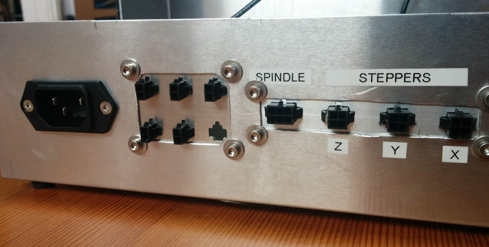
The 5 new Micro-Fit connectors in the back panel. The three on top are for the XYZ limit switches, the two on the bottom for the coolant solenoid and general 12V supply. There’s a spare hole, too.
The internal wiring for the limit switches was pretty easy, a single piece of ribbon cable between the limit switch connector on the Arduino shield and the three 2-wire connectors on the back.
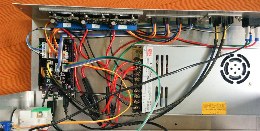
With the limit switches and the wires to the coolant and 12V connectors done, the internal wiring of the electronics box should be complete.
When I hooked up the switches for testing, however, they did not really work. I had not bothered to add any filtering to the switch lines on the circuit board, but hooking up the switch inputs to the oscilloscope showed that whenever the motors were energized, there was over a Volt of induced noise on the line. There were also severe contact bounces. Finally, the inputs use the 3.3V internal pull-up resistors on the Arduino, which on the Due are 100k Ohm. This does not make a very strong pull-up.
Reading a bit on the web showed that people seemed to be happy with limit switch performance using external, 330Ohm pull-up resistors and a RC low-pass filter consisting of a 10k resistor and 0.1uF ceramic capacitor. This gives a filter time constant of 1m, plenty fast for what we need but still much longer than the frequencies of the noise features.
The problem was of course how to add those components… It took a little soldering gymnastics, but they are now ghetto-hacked onto the back of the circuit board. That shield is getting pretty crowded with deadbugged components and jumpers. (At least version 2 of the circuit board, if one is ever ordered, will have all these issues fixed…)
With the noise filters, the switches perform flawlessly. I have also enabled the TinyG soft limits, so after running a homing cycle, it now refuses to perform moves that it knows will run into the end stops, which is nice. That has definitely happened too often, from mistyping commands. Of course, this only works with the fixed end stops, not for running the Z-axis down into the table or crashing the end mill into the vice, so caution is still necessary.
The movie below shows a G28.2 homing cycle with TinyG.
Pingback: CNC Mini Mill #9: Spindle and coolant control | Patrik's projects
hello!
Just getting ready to add limit switches to my Probotix setup. I know nothing about wiring but the diagrams is simple and I can send to you if it helps. Is there is a way to add “external, 330Ohm pull-up resistor & RC low-pass filter consisting of a 10k resistor and 0.1uF ceramic capacitor” directly inline instead of on the board? Thanks for your time