The Experimental Aircraft Association has been running these workshops teaching different aircraft building skills around the country for a long time, and when I saw that the Composite workshop was going to be offered in Riverside, I jumped on the opportunity to get some momentum on my airplane building project. (It was apparently a good idea, too, because our instructor, John Brecher, said this was the second to last one. From now on they’re only doing them in Oshkosh…)
We worked on two little pieces, a flat piece of foam we glassed, cut in half, and then joined together with a fillet joint and a small section of an airfoil that we hot-wired in polystyrene foam, added spar tapes top and bottom, and then skinned with fiberglass. This took two full days, mostly because of the need for the epoxy to cure for 24h between each layup. I’ll let the pictures speak for themselves below, but it was a nice introduction to the techniques used and it doesn’t seem that hard. Of course, like I said at the end of the workshop, being able to manufacture some pieces is one thing, trusting them with your life is another…
-
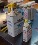
- This is the resin we used, West system 105 + hardener.

-
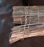
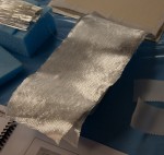
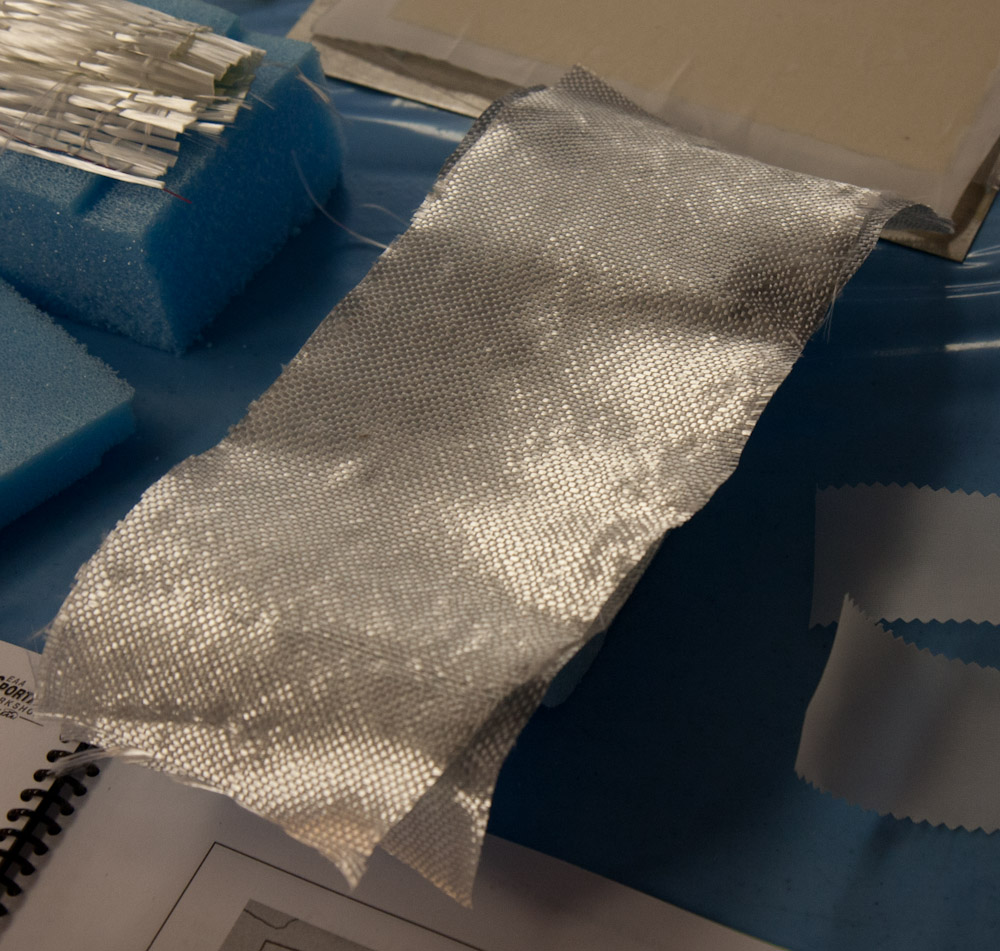
- This unidirectional fiberglass tape is used when you need all strength in one direction, like the spar tape next.
-
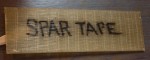
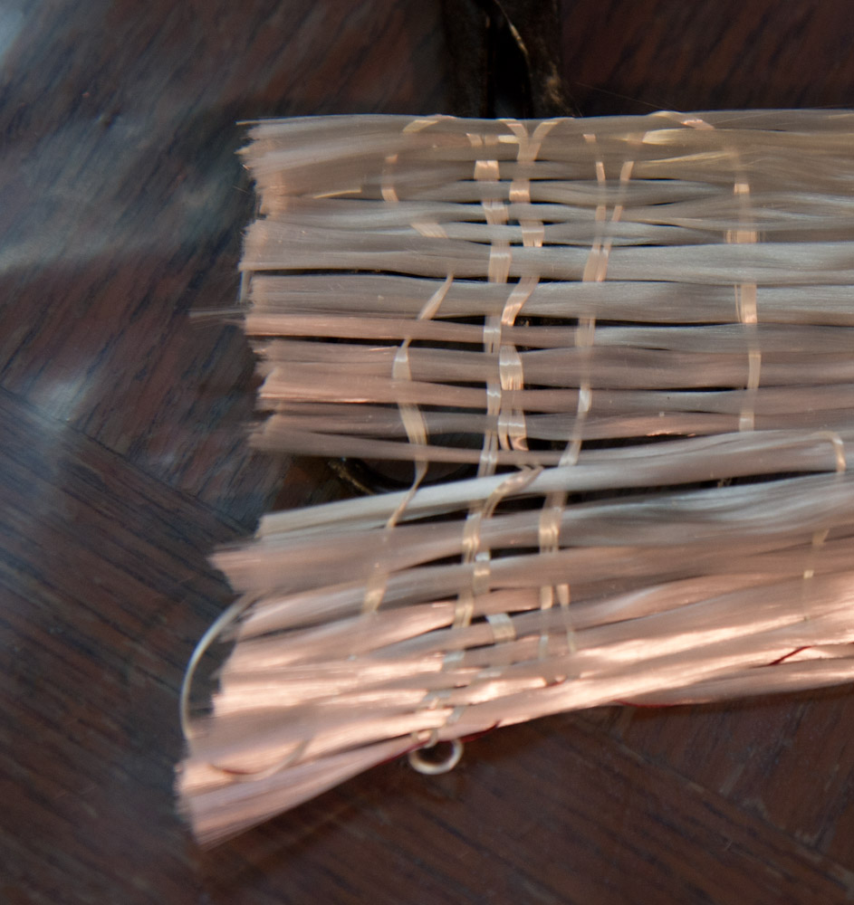
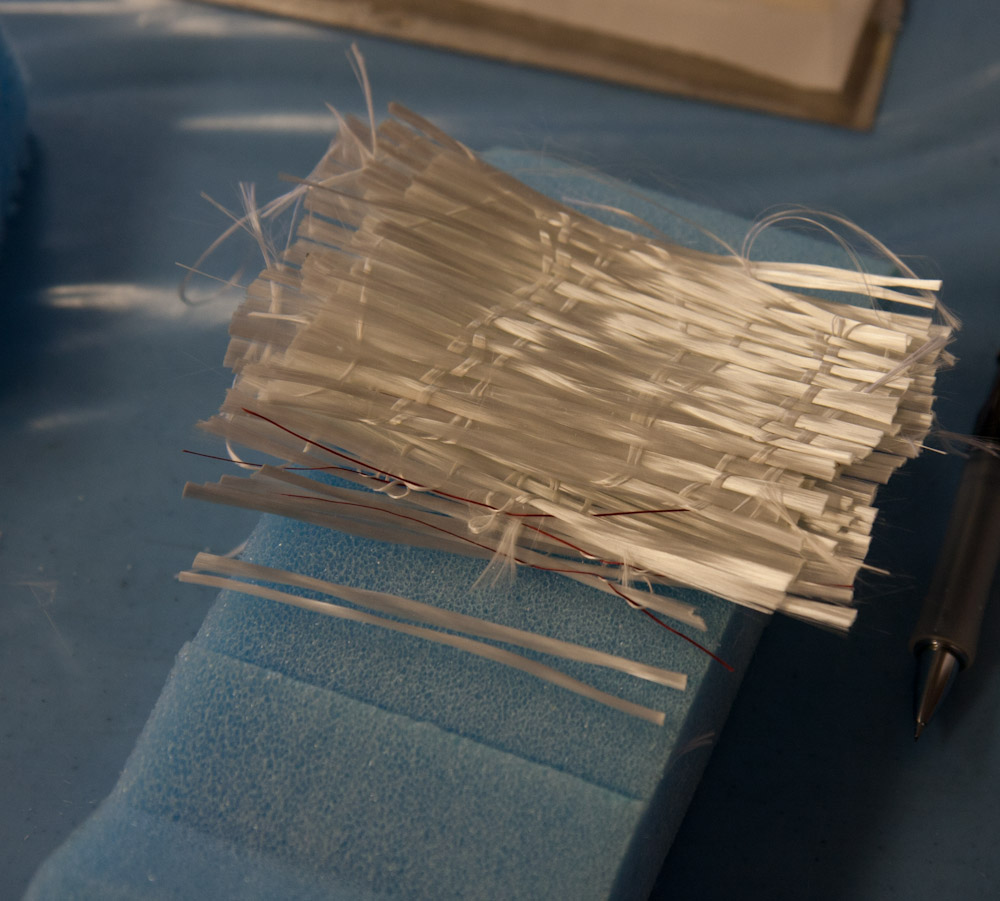
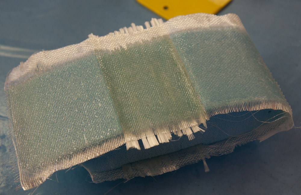
- This spar tape is made up from multiple layers of the UNI tape on the previous picture. It’s maybe 5mm thick and completely rigid in the fiber direction, while noticeably flexible in torsion.

-
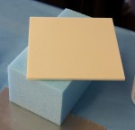
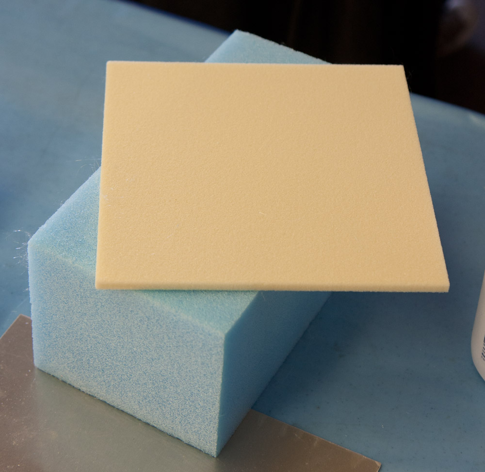
- This is the foam we used. The gray sheet is polyurethane, the blue polystyrene.
-

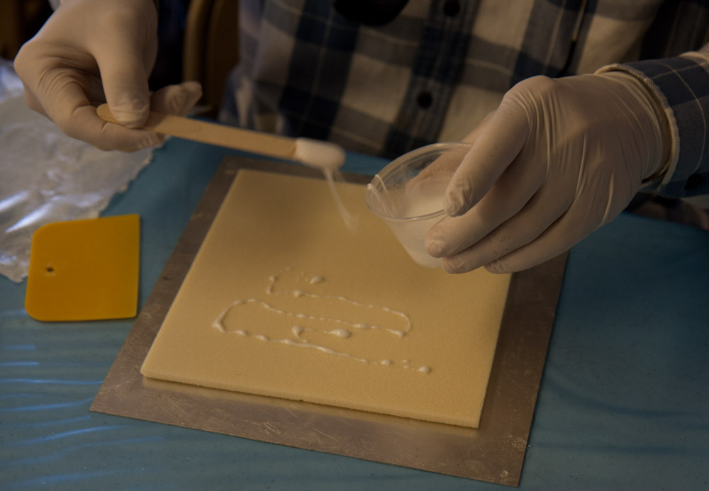
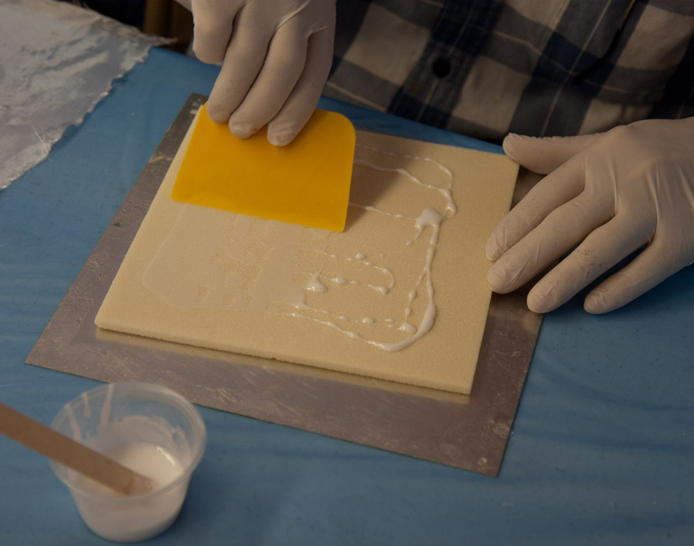
- The first step is to apply micro slurry to the foam surface. This fills the open cells on the surface of the foam and ensures a good bond between the glass and the foam.
-
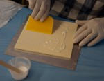
- The micro slurry is scraped into the foam cells with a squeegee, ensuring that only a thin layer is left on the surface.
-
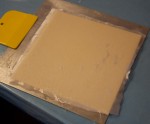
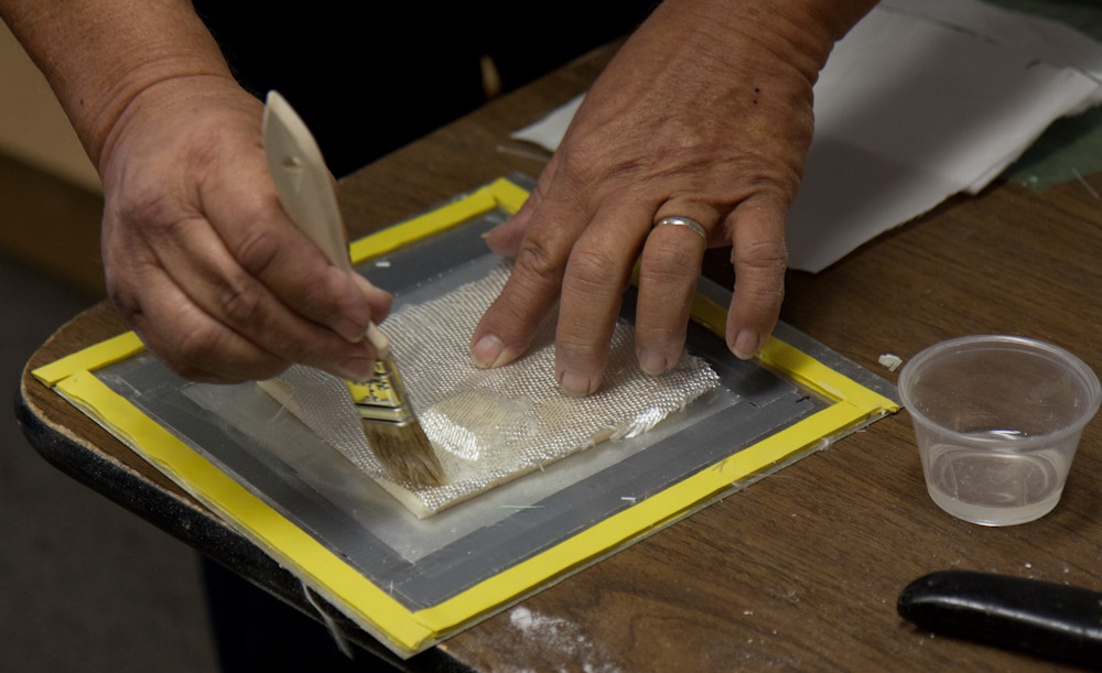
- Then the fiberglass cloth is added, and the epoxy resin worked into the fibers so that there’s no air bubbles. (I haven’t done such a good job here.)

-
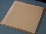
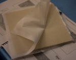
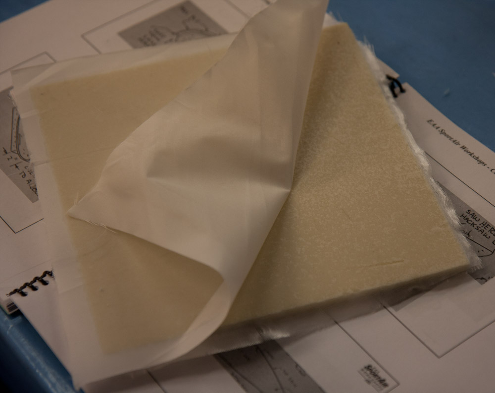
- The final step is to add “peel ply”, a layer of Dacron fabric which the epoxy doesn’t stick to. After the expoxy has cured, this can be peeled off (hence the name), exposing a fresh, textured surface for bonding additional layers of fiberglass to. This saves you from having to sand the surface to get a good bond.
-
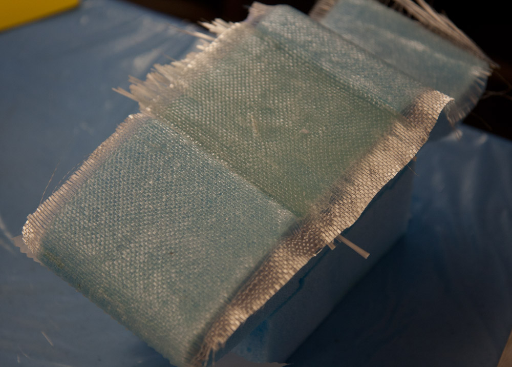
- On the second day, we removed the peel ply, exposing the fiberglass.
-

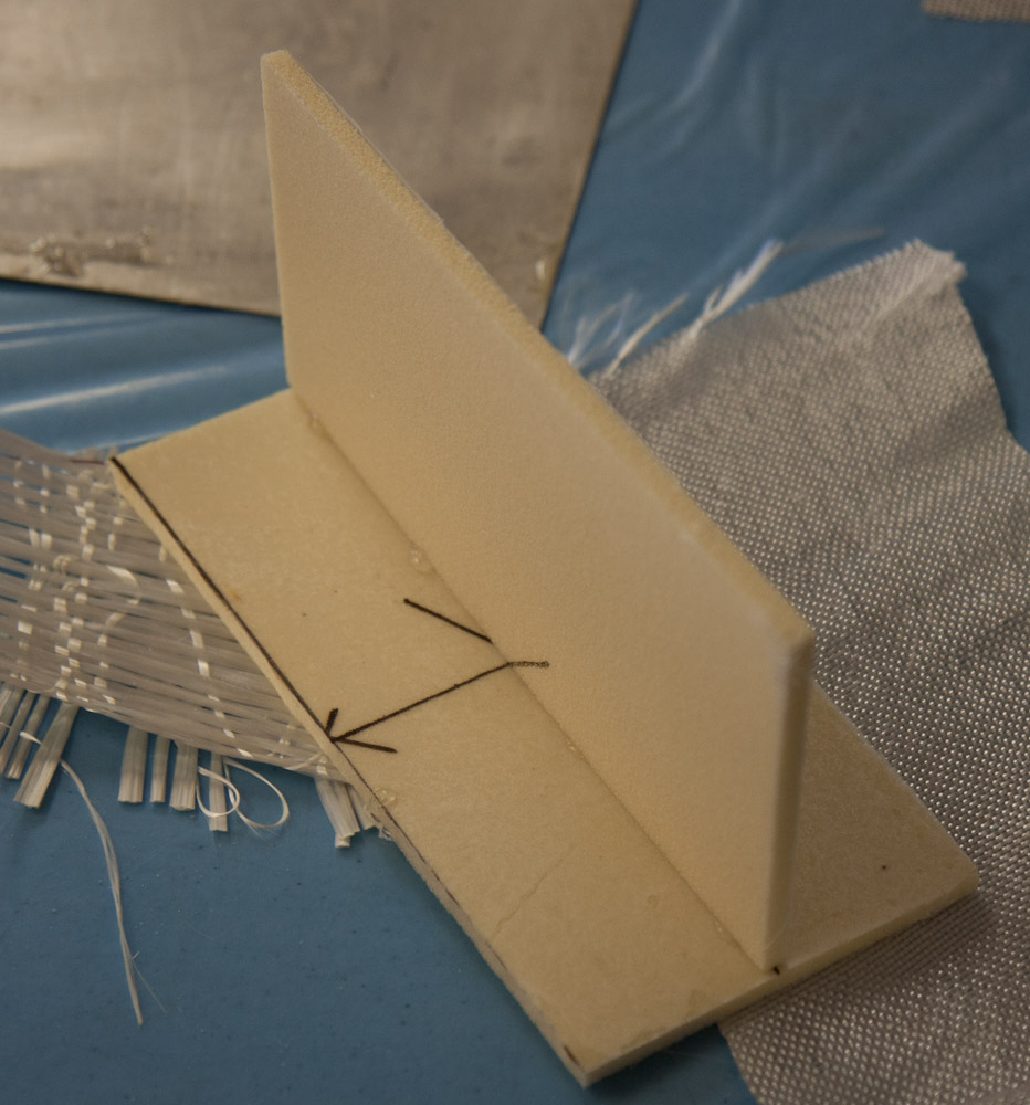
- The object was now to make a T-joint. The first step is to just fix the pieces with some hot glue to hold them in place while the glass is being applied.
-
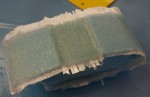
- This is the final joint after applying peel ply. It was a bit messy and I didn’t want to get epoxy on the camera so there are no pictures of the intermediate steps. Basically you first fill the corner with thick micro to make a radius that the cloth can follow. Then three layers of glass of increasing size were added over the corner, followed by the peel ply.
-
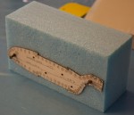
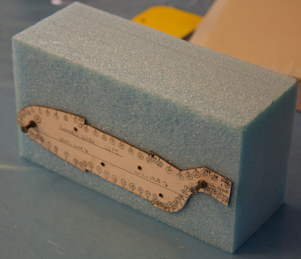
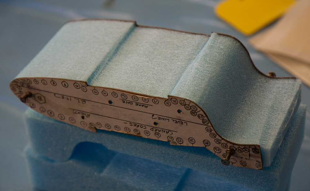
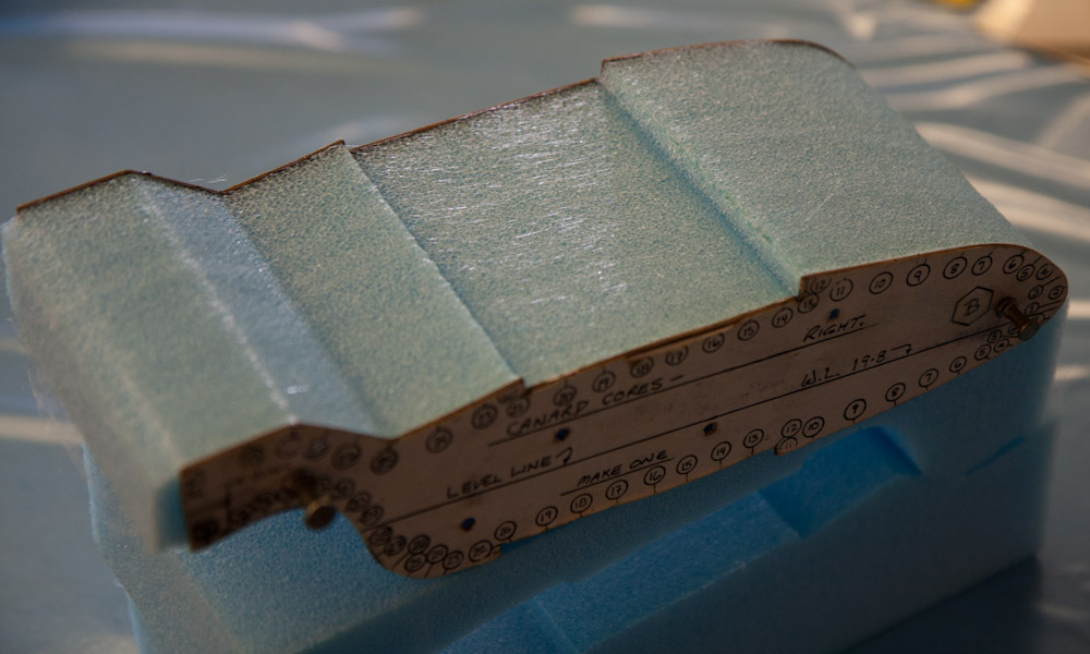
- To cut the airfoil, we started by mounting the templates, one on each side of the foam core, making sure they are parallel.
-
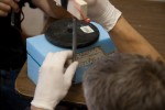
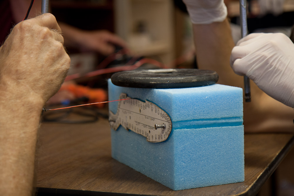
- Then you cut the foam using a steel wire stretched between two posts, heated to red hot using a variable transformer. By sliding this along the template on both sides, you cut the exact shape into the foam. If all goes well…

-
- Here, the bottom has been cut and they are working on the top.
-
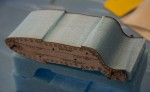
- This is what I ended up with. It’s pretty good, but you can clearly see some artifacts where we weren’t quite at the same point on both sides. Staying synchronized so you don’t cut diagonally is the big challenge.
-

- The top surface came out better. The “tab” on the left is the trailing edge. It will later be cut away, but not until the bottom has been glassed.
-

- The first step is to lay up the thick spar caps on the top and bottom using the unidirectional tape.
-
- Then we cut these pieces of BID that will become the surface skin.
-
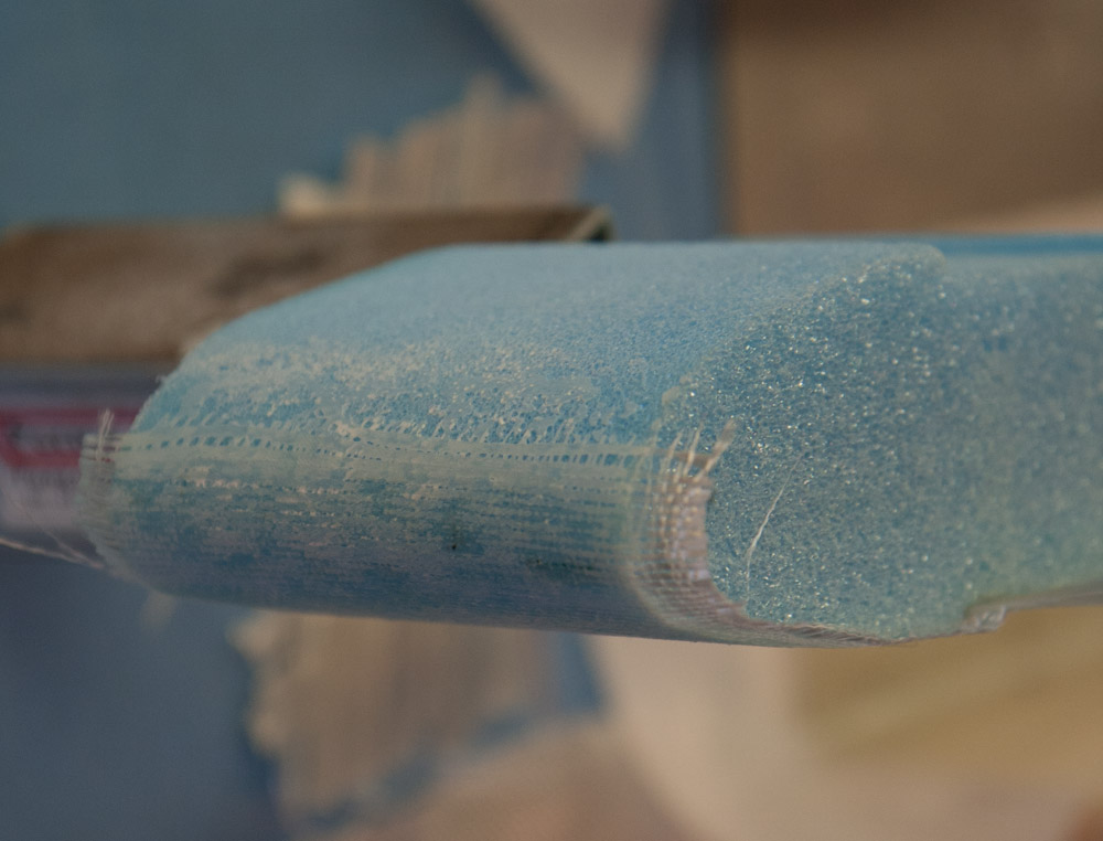
- Here I’ve done the bottom spar tape and skin. The glass looks a bit dry.
-
- This is the trailing edge. When we cut the foam “tab” away, the top skin will join this part, making a sharp end.

-
- On the leading edge we put peel ply where the cloth ends. This makes the fibers lie nicely flat against the surface so the other side will overlap cleanly.

-
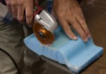
- After curing, the excess glass can be trimmed with a handy multi-tool.

-

- The leading edge after removing the peel ply. A small ridge of resin is visible that will have to be sanded down.
-
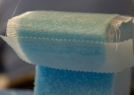
- Here the top side of the airfoil has been laid up with spar tape and skin. Note that the foam “tab” is now gone and the trailing edge tapers to a thin edge.
-
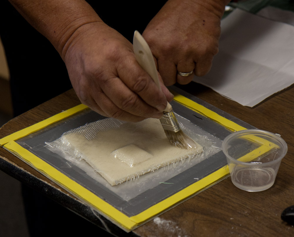
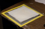
- The final technique that was demonstrated (we didn’t make one each) was vacuum bagging where you cover the object in plastic and pull a vacuum that “squeezes” excess resin out. Here we’re starting with a flat foam piece with a little shaped object in the middle.

-

- Then you add epoxy normally.
-

- Though you don’t have to worry so much about getting too much epoxy in the fibers, since it will get squeezed out.
-
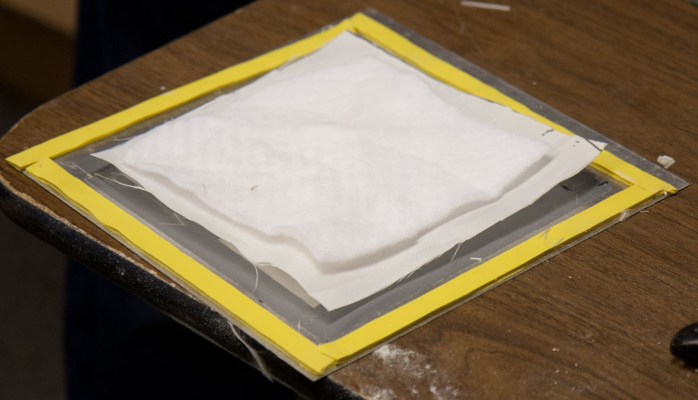
- Add peel ply on top as usual.

-

- This “padding” is a thick material that will suck up excess resin and enable the vacuum to get everywhere across the piece.
-

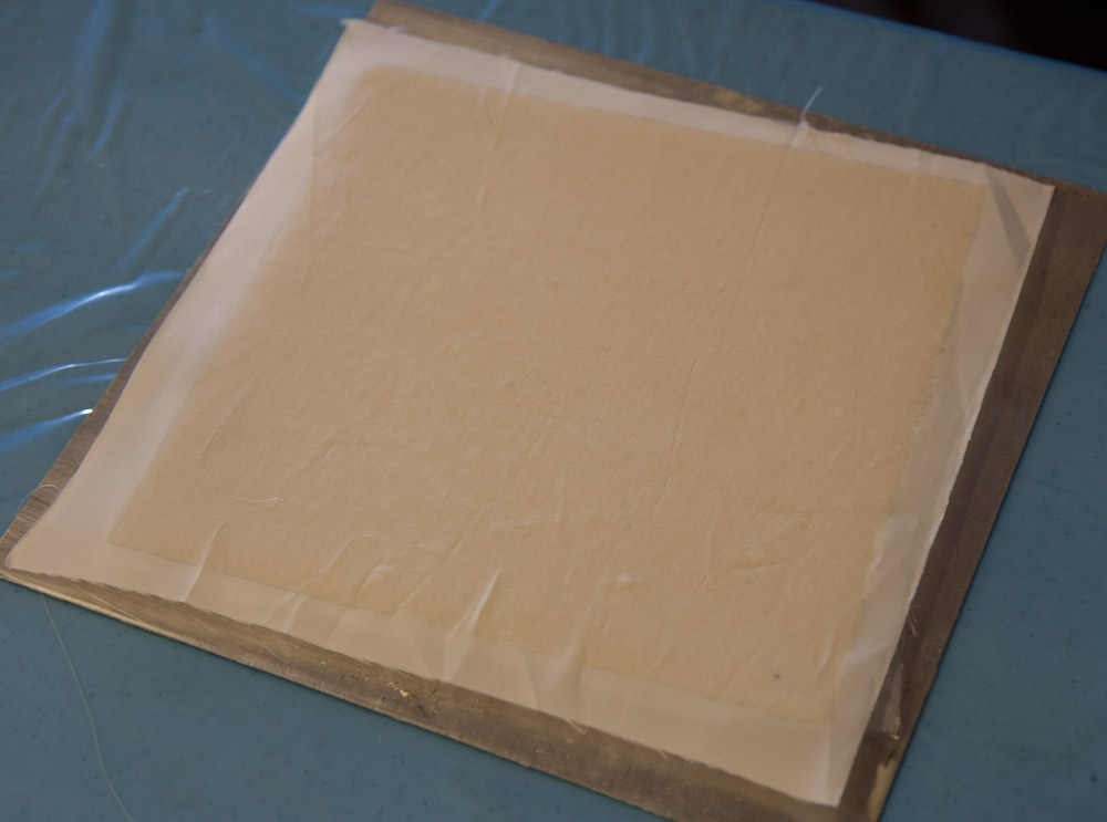
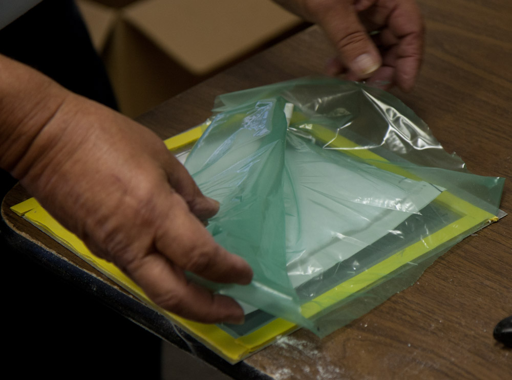
- Then the entire layup is covered with plastic.
-
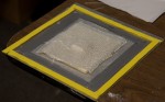
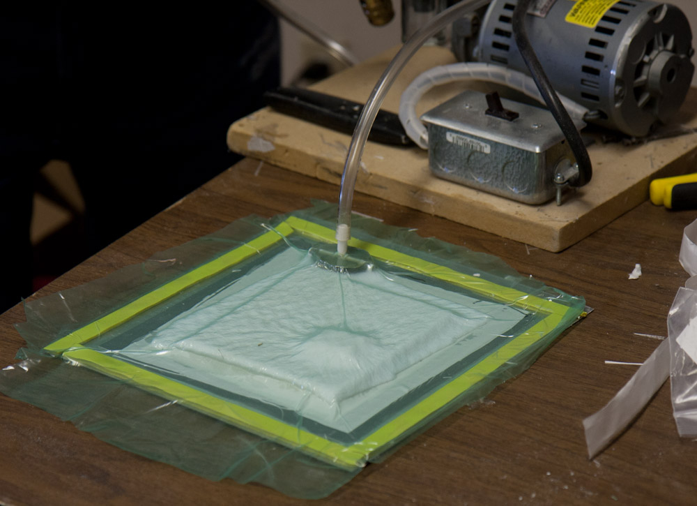
- The plastic obviously needs to be totally sealed. The yellow is a very sticky double-sided tape that’s used to attach the plastic. The little pipe poking out is where the vacuum pump is attached.

-
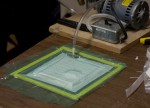
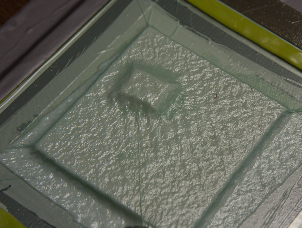
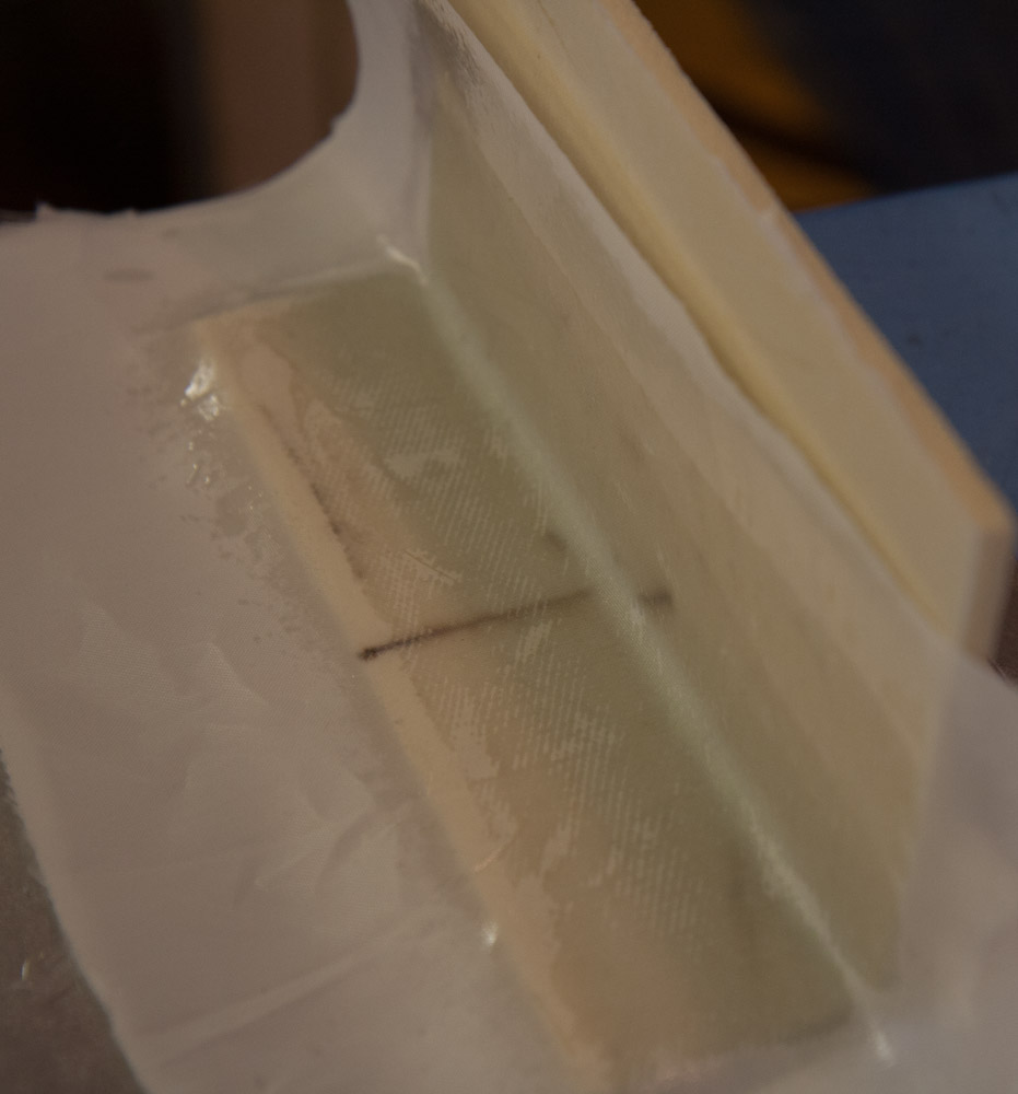
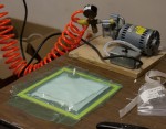
- When the vacuum pump is turned on, it sucks the plastic tight against the surface, making sure there are no air pockets in the epoxy or between the glass and the foam.
-
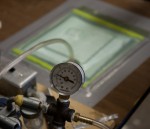
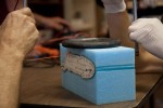
- After sealing the piece with some extra duct tape visible in the background, the vacuum was up to 24 in Hg, which is sufficient.

-
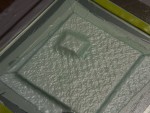
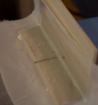
- You can clearly see how well the cloth is conforming to the shape of the foam piece. Unfortunately I don’t have any pictures of the piece after curing, because it didn’t really have time to cure fully before the workshop ended.