This is post #4 describing the wine storage unit upgrade. See the introduction post for the background.
If you’re read the previous posts, you have an idea of what functionality I have in mind. What remains to be made is the main circuit board that will house the microcontroller and the driver circuits for the thermoelectric element and the two fans, and then the hardware modifications to the unit.
The fans are controlled with switching regulators as described in the article “Voltage Regulators Rev Up PWM-Based Fan Control”. The common MC33063 switching regulator converts the PWM output from the microcontroller to a nice, smooth output for the fan. (I used to drive the fans in my computer with PWM directly, but the switching of the voltage creates audible noise in most fans, so this is much preferable.)
Because we want to be able to run the thermoelectric element in both a cooling and heating mode, it is connected to an H-bridge which is driven by another PWM output on the microcontroller. (When figuring out how to do this, I came across this excellent series of writeups about H-bridges. If you are interested in how they work, I encourage you to check it out. Since we aren’t controlling an inductive load like a motor, we shouldn’t have to worry about the bypass diodes etc that are described in those articles, though.) The H-bridge has 4 MOSFETs controlled by two ADP3120A driver chips that deal with boosting the voltage to the high-side transistors and preventing shoot-through conduction which would quickly overheat the transistors. The two sides of the H-bridge are controlled by the two PWM outputs connected to Timer1 on the Atmega (which means they switch in sync) as well as a common disable line that will pull the gates of all 4 transistors low.
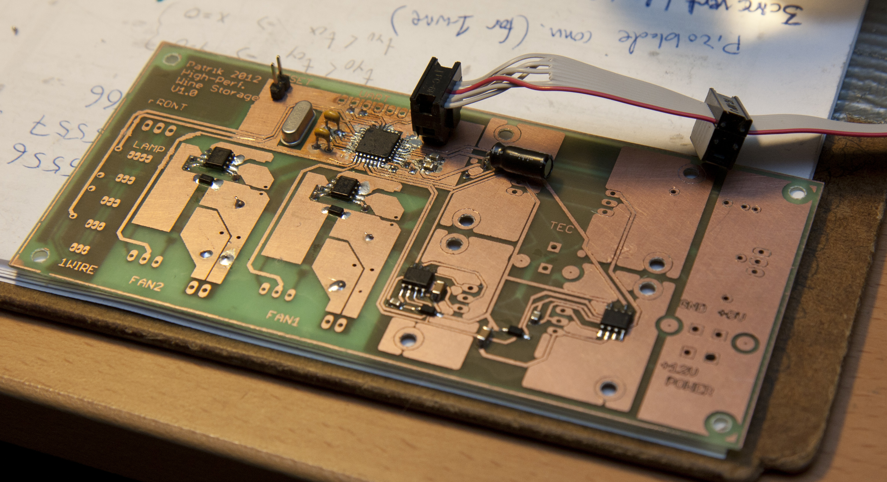
With the two switching regulators, the H-bridge, the Atmega328 microcontroller, and the connectors to the front panel, lamp panel, and the 1-wire temperature probes, it ended up being a fairly large circuit board. Here’s what it looked like after soldering all the surface mount components and enough other stuff to be able to test that the Atmega could be programmed through the ICSP interface.

The main board, with surface mount components soldered and the Atmega connected to the AVR programmer. On the lower left are the two switching controllers (marked FAN1/2) , and the right half of the board is the H-bridge (with space for heat sinks for the power transistors).
I did run into some trouble making this board. The first iteration had too narrow spacing between all the fills and the conducting parts, so there was loads of short circuits. I redesigned it and tried to etch a new board, but for some reason the toner transfer failed repeatedly. In the end I said “screw it” and went back to the first board — it ended up being easier to cut the shorts than to make a new board. (The reason for the large isolated fills is that the toner transfer seems to work better if there are large filled areas. Single thin connectors by themselves almost always end up not transfering correctly.)
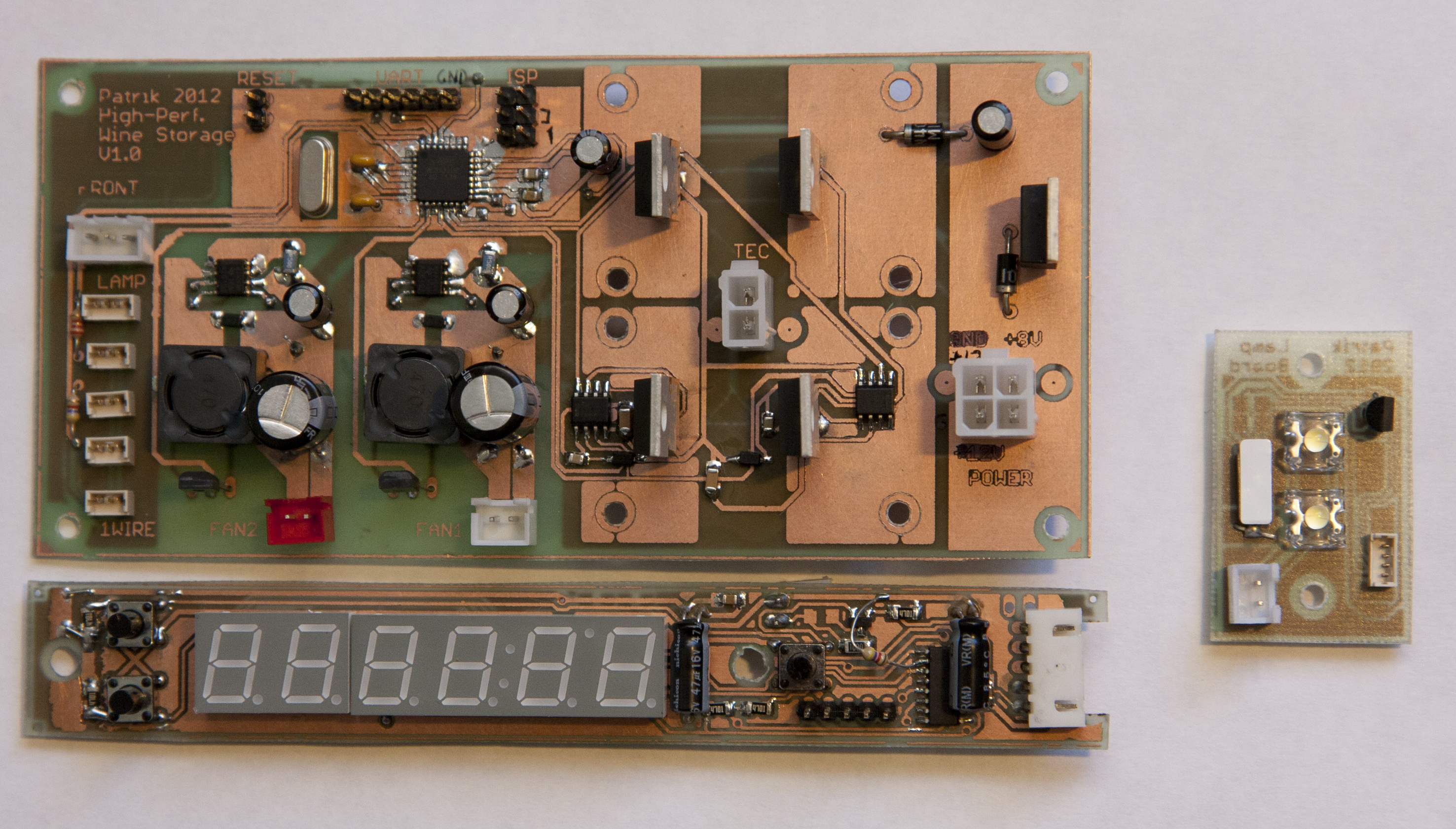
In the end, this is how all the boards look fully populated, except the heat sinks for the H-bridge MOSFETs (which may not end up being necessary).

Here are the three circuit boards, fully populated (except the heat sinks for the power transistors for the thermoelectric element.)
It all worked pretty well, but what trouble there was came with the H-bridge. The thermoleectric element pulls about 6A at 12V, i.e. about 70W, a fair amount of power compared to most digital electronics stuff. This means there’s enough power to burn stuff out if you accidentally short something, so some care needs to be maintained when poking around with the oscilloscope probes. Since it runs with PWM, it switches on and off, and this puts all kinds of switching noise onto the power lines which screwed up a lot of things. But first a few hardware changes were necessary.
Pingback: High Performance Wine Storage System #3: The Lamp Panel « Patrik's Projects