This is post #6 describing the wine storage unit upgrade. See the introduction post for the background.
Time to start testing things. I had managed to burn the Arduino bootloader onto the Atmega 328, and I had previously written some test code to exercise the front panel LED display. The big thing to test now was the H-bridge to the cooler. This turned out to be more of a problem than I’d anticipated. Suffice to say that I’m not very experienced with switching circuits, and the amount of noise generated when the bridge turned on was a way bigger problem than I’d anticipated. It screwed up the communication to the temperature probes, and initially it would even reset the Atmega when it first turned on. Highly suboptimal…

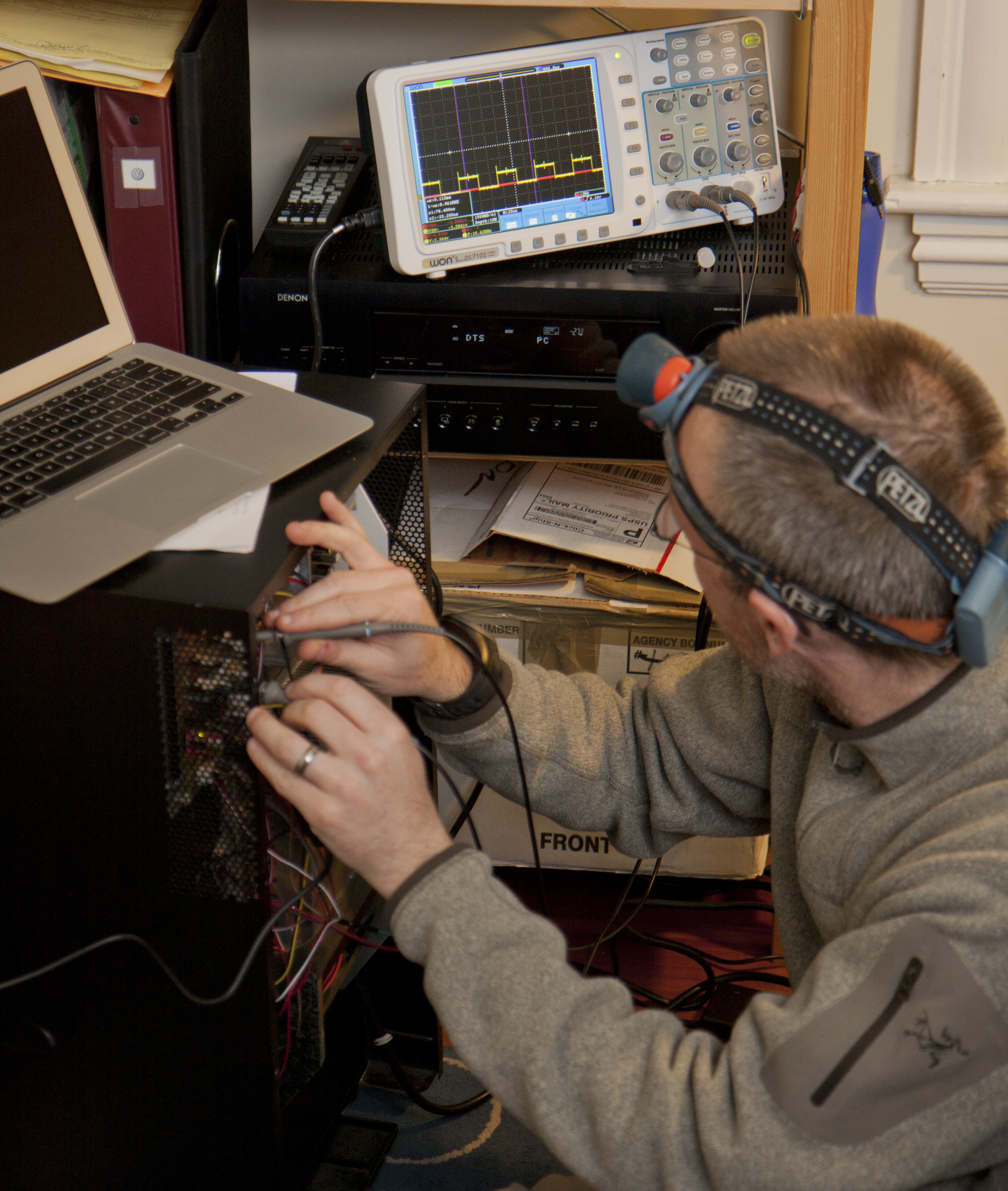
This is me trying to figure out what the problem was with the H-bridge. I'm really happy I got that oscilloscope, without it I would have been totally stumped!
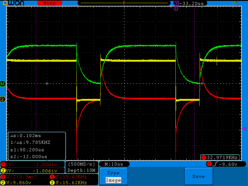
The key realization was to put an inductor in series with the thermoelectric element. This prevented the current rush and made everything much more well behaved. Below is a screenshot of the oscilloscope showing the inductor and thermoelectric element voltages during the switching cycle. There are still substantial spikes at the switches, but it’s at least low enough to not reset the Atmega microcontroller.

The switched output to the cooler using a 5uH inductor. The yellow line is the H-bridge output voltage, the red line the voltage across the inductor, and the green line (which is yellow minus red) the voltage across the thermoelectric element.
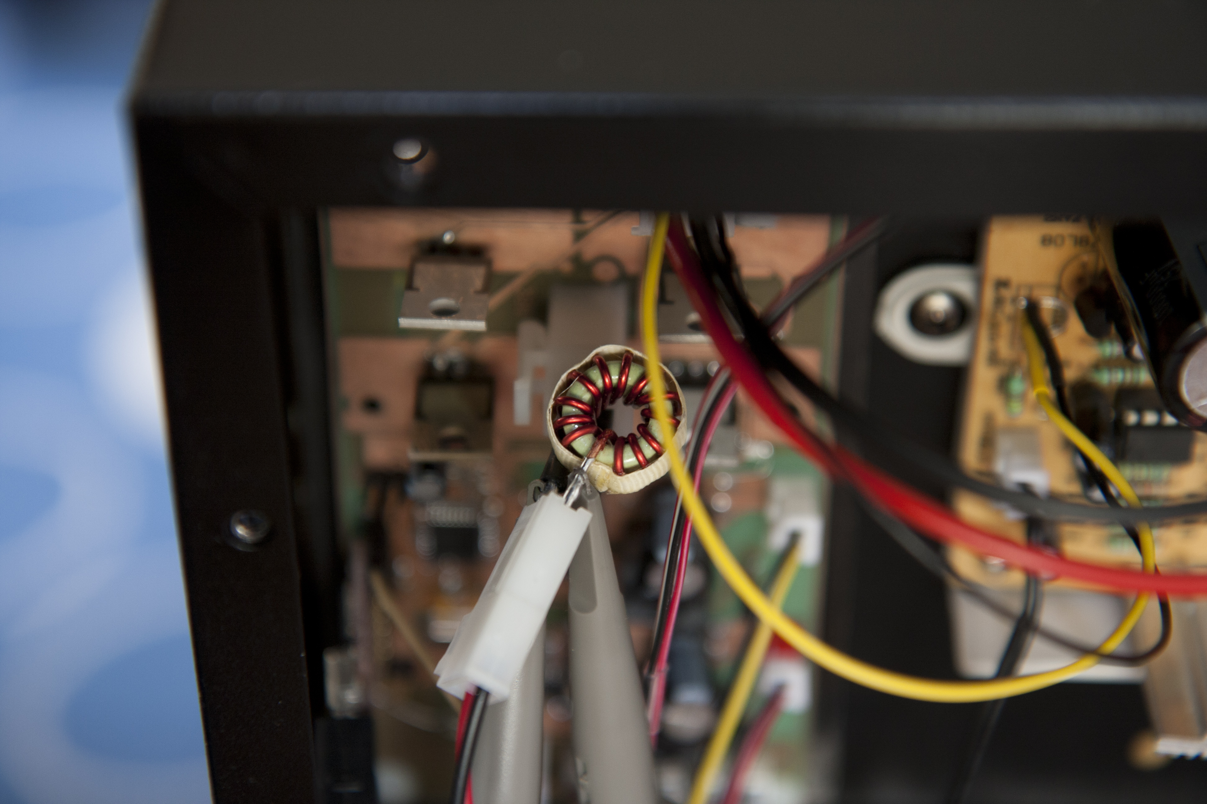
The communication with the temperature probes now worked fine, but the front panel was still a problem. Since there’s much more data going that way, it was running in 1-wire “overdrive” mode, so the speed was higher. Even after adding a number of bypass capacitors by the connectors to the 1-wire probes, it would still refuse to communicate. (I found this good article on “Power Supply Noise Reduction” that I wish I’d read before designing the circuit board. There were some rules of thumb, obvious in highsight, that I wasn’t aware of.) Since there was no way I could put an inductor on the board, I ended up making a little “extension cord” to the connector to the thermoelectric element. It looks a bit hoaky, but this is prototyping at its finest…

The connection to the thermoelectric cooler, with the 5uH inductor retrofitted as a short "extension cord" before connecting the cooler.
To “solve” the communication problem, I resorted to just turning off the cooler while sending things to the front panel. This lowers the maximum cooling power a bit, but it only takes a few milliseconds a couple of times per second, so it’s not a big deal.

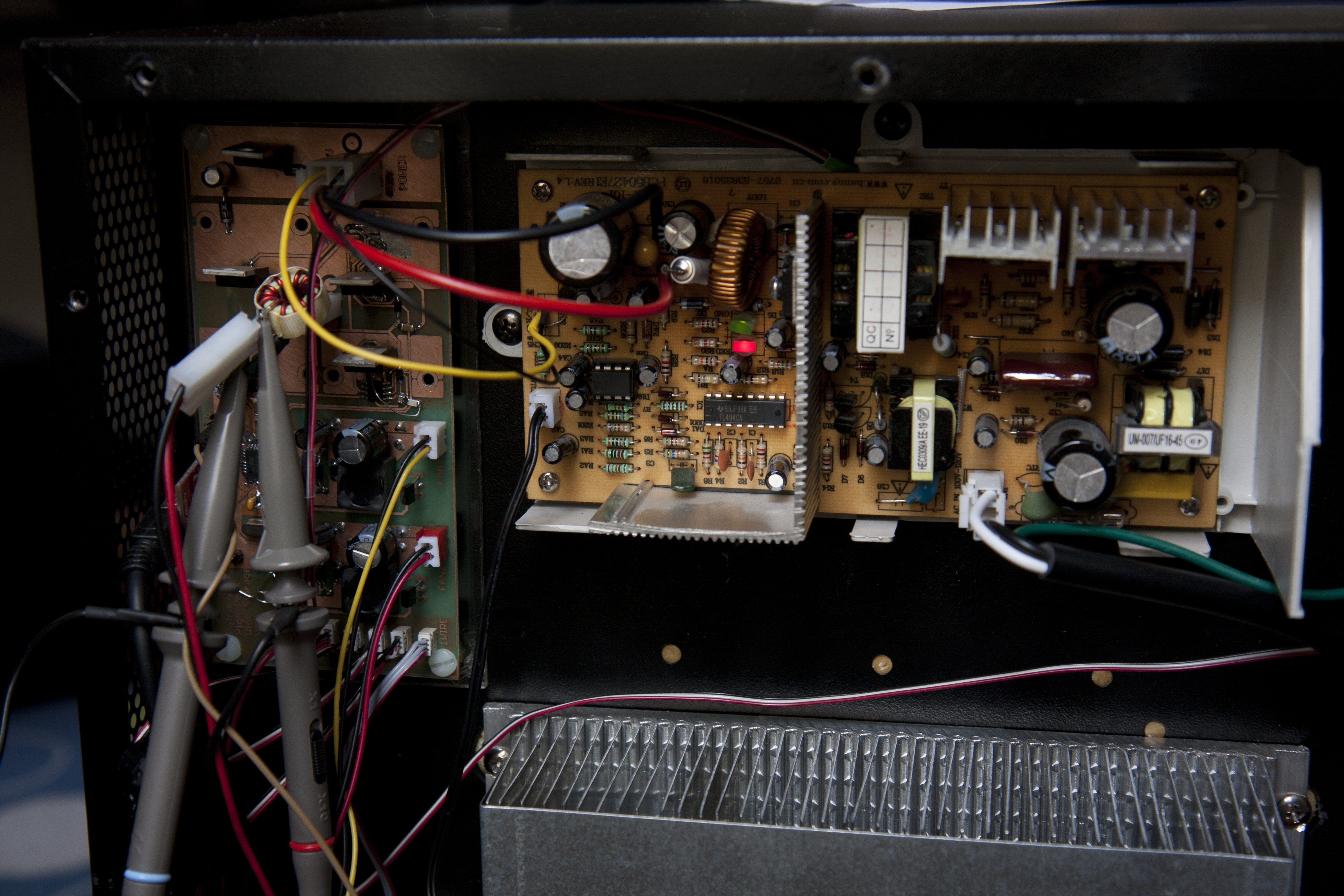
The circuit boards on the back. To the right is the power supply board that was originally there, on the left (with the oscilloscope probes attached) the board I made.
The biggest remaining problem was that I kept burning out the ADP3120A driver chips for the H-bridge. It was always the same one, the one that should just keep the low-side MOSFET on continuously during cooling operation. After replacing 4 of them (at about a buck fifty each) I said “screw it” and just hardwired that MOSFET to be on all the time. I can live without heating ability for now, especially since we’re moving to LA and are unlikely to need to heat the wine in the foreseeable future. I really don’t know what was going on, I double checked the wiring several times and the to 3120’s were connected exactly identically.
I also ended up with an even bigger “event”: After adding the inductor, there was an uncomfortably large voltage spike when the bridge turned off, -35V or so. This is apparently expected according to the H-bridge articles I had read and is because it takes a while for the internal source-drain diodes in the MOSFET to start conducting. Since the inductor current has to flow, the inductor voltage builds up quickly. The solution recommended in those articles were to put a capacitor across the H-bridge output, so the current would go into charging the capacitor until the source-drain diodes start conducting. Not having any indication of how big such capacitor should be, I took one of the plentiful 1uF SMD capacitors I had. After soldering this on, the power supply would refuse to start when I plugged it in. (It has a LED that indicates whether the output is at 12V.) This seemed very strange, but after a few tries it started. However, when I attached the oscilloscope probes, I saw to my horror that both the 5V and 12V rails were swinging to +-10-20V. I have no idea what caused this, but the Atmega did not survive! When I changed the capacitor to 470pF, everything seemed fine and I haven’t had any problem since.
If anyone has any idea what might have caused this, please let me know. The weird thing is that the H-bridge shouldn’t even be on when the power comes on, the disable input to the ADP3120A is pulled down and I’m pretty sure the Atmega outputs start up as high-impedance inputs…
After desoldering the Atmega (lucky I got that heat gun) and attaching my spare one (another $4.50 in the trash can) it finally seems like things are behaving. Time for the final tuning of the software and testing how well the temperature regulation works.
Pingback: High Performance Wine Storage System #5: Hardware « Patrik's Projects