While I took the Z-axis apart to replace the spindle on the CNC mill, I made another discovery. I already mentioned in that post how the thrust bearings for the Z-axis ballscrew were shot, but another thing that puzzled me since the day I got the CNC conversion kit was that it appeared that the ballscrew (which was pre-mounted in the thrust bearings when it arrived) was cocked in the bearings.
I even emailed CNC Fusion, who made the kit, a video and asked whether it was supposed to be like that, and they said basically “we’re not sure what’s going on but if something’s wrong we’ll fix it.” However, at that point in time I had no real way of checking this and it was subtle, so I elected to put the kit together and start using it. Well, this is the first time that this part has been off since then.
Once I took the ballscrew and bearings out, it was clear that something was wrong.
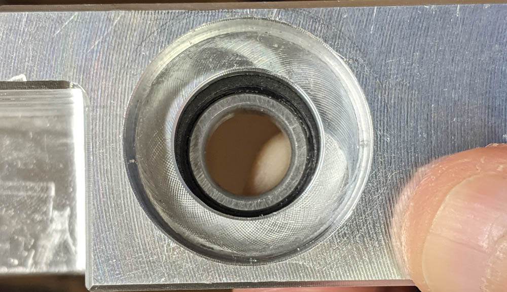
This is looking at the lower thrust bearing down from the top. The bearing race looks pretty much concentric with the hole.
The thrust bearings are mounted in a bracket that also holds the coupler and Z-axis motor. They fit into recesses on two sides of this bracket such that when the bearings are tightened onto the ballscrew, the outer races are preloaded against the bracket and prevents the ballscrew from moving, only letting it rotate.
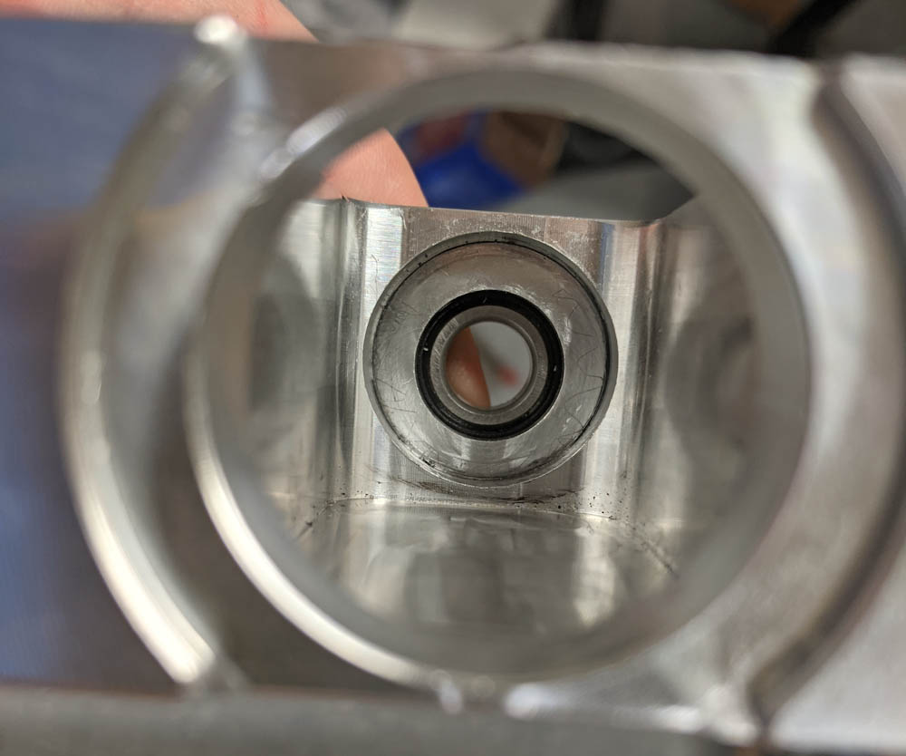
Viewing the upper bearing from the bottom of the mount. This bearing is clearly not concentric with the hole.
Once I started examing this mount, it became clear that the two bearings, when mounted, were not concentric. By its very nature, you have to machine the slots that the bearings sit in from opposite sides, in different setups, and one of these setups must have used an incorrect part zero. Or it was just designed wrong.
This is the second axis mount that has turned out to be incorrectly made in this kit, back when I got it I noticed that the mount for the X-axis motor also did not line up the ballscrew with the thrust bearing on the opposite side. That was a serious problem and I had to make a small plate to correct that right away. This error is more subtle but obvious if you examine the part, so at this point I’m not very impressed with their QA. (They’ve since gone out of business, so there’s that…)
In any case, this probably explains why the Z-axis ballscrew always seemed to have a tendency to wobble. Now that I know about it, I’ll just make a new, correct, mount. Before I put the Z-axis back together I measured and CADed up this part.
I might wait until the new spindle with angular contact bearings is mounted, though. In the few jobs I’ve run since assembling the spindle with the new bearings, I noticed that surface finish seemed worse. The SuperFly cutter, in particular, exhibited a noticeably ringing sound when cutting, and you could tell from reflections in the surface that the cutter was oscillating up and down. The oscillation frequency seems independent of spindle speed and is quite high, I’d say a few kHz by ear. The only obvious potential cause for this is that the new spindle bearings are less rigid than the old ones, perhaps because I now have too little preload. In any case it seems prudent to wait for the new bearings to be mounted. Now that I know what to do, you don’t even have to take the head off to disassemble the spindle, so it shouldn’t take long.