The previous post talked about how we arrived at the present unpainted state. Before painting, there were some things to attend to with regards to the rear fairing. This is still the early Tyga version, and it also has some fitment issues.
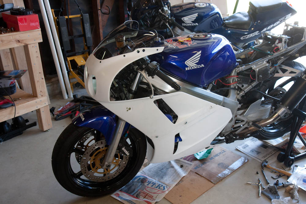
In case you don’t remember, this is how the bike looked when I bought it.
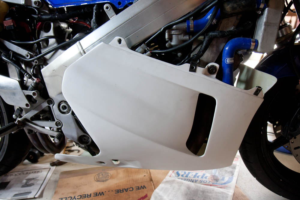
Look at the rear fairing above. The only places where it’s attached are with the four screws (two on each side) at the front end, under the tank, and where the front of the seat hooks into the tank. The entire part rear of the seat is unsupported! The rear end flexes easily an inch up and down when attached, with most of the flex happening at the rear end of the seat there the profile is the lowest. The paint is actually cracking in this area, presumably from being flexed continuously while in motion.
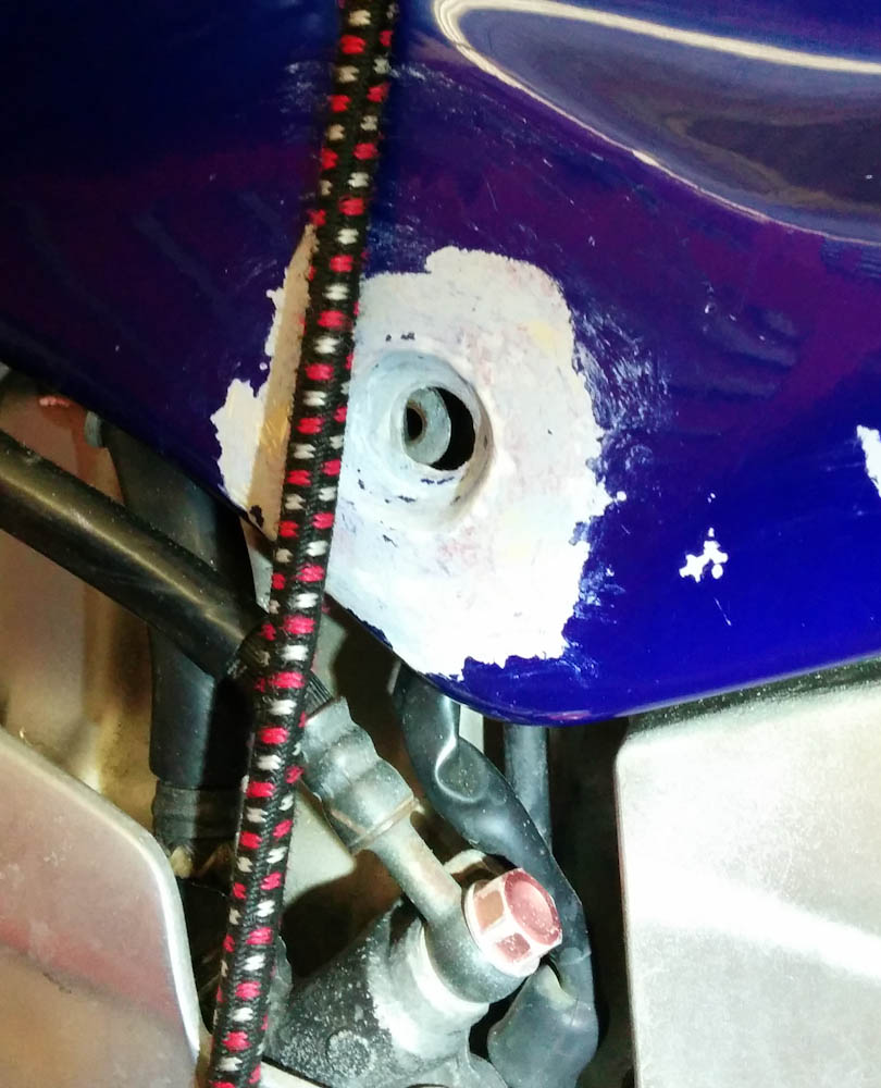
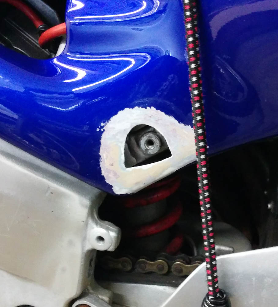
The second problem is that the screw holes don’t fit the frame (you should have guessed this was coming by now.) The distance between the two holes isn’t correct. When the front screw is attached, the rear hole looks like this:
This is how the rear hole lines up with the mounting point in the frame. Or rather, how it does not…
When mounting this piece, you had to push the fairing hard to get the screw to thread in, and over time this side load had completely obliterated the threads into the aluminum frame. If I’m going to put in a bunch of effort painting this piece, I want it to fit properly. So after a bit of agonizing, I decided to trust my fiberglass skills and “get medieval on its ass” (in the unforgettable words of Marcellus Wallace):
After cutting out the old screw hole, I can now make a new one…. I hope.
The idea is to lay up a new mounting hole here, but in the right place. I’m not exactly sure what the best way for modeling the depression for the screw head is. Probably making a plug to fill the hole first, shaping its outer surface to the right shape. Then making a mold of that against the outside. We’ll see.
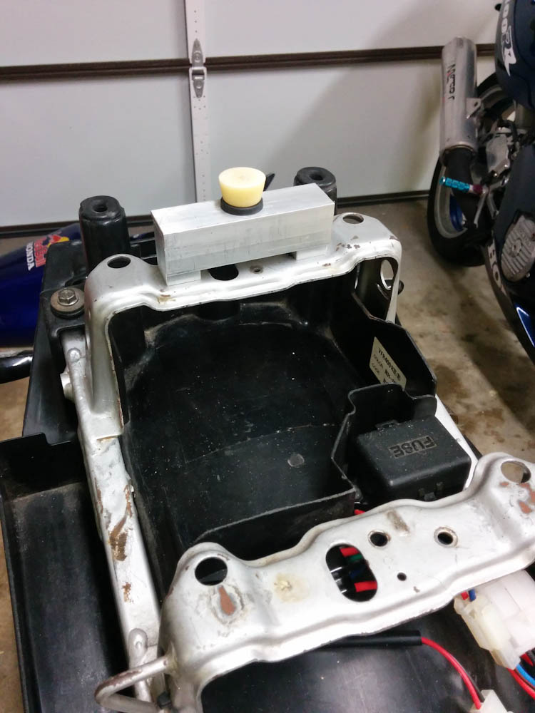
The other thing that I wanted to fix was to make some sort of support for the rear end of the fairing so it can’t move around. There are two steel rails on the subframe that are meant to support the rear seat. Since I don’t have a rear seat, I decided that I could add a support on top of the rear one and make the fairing key into a hole in it.
The short piece of aluminum angle on the rear bracket holds a grommet that a point on the fairing will key into.
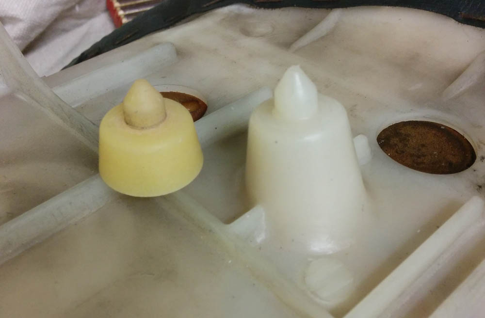
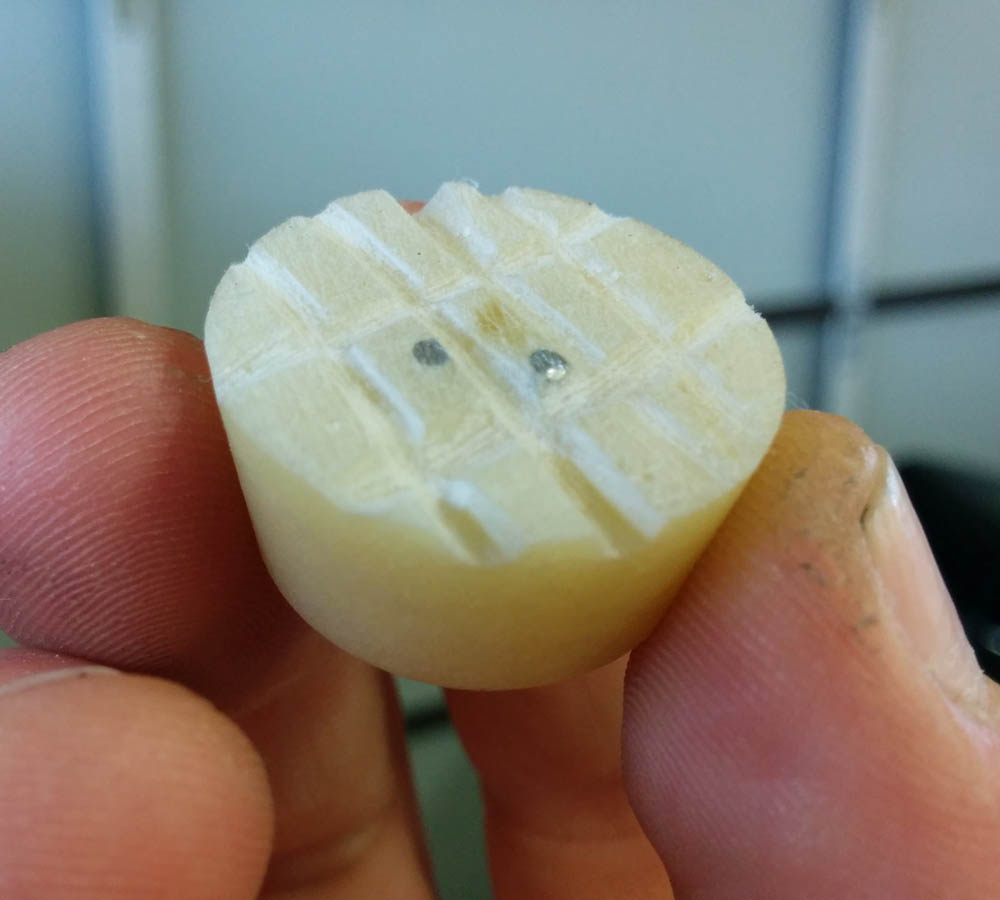
I molded the “point” that will key into the grommet from the ones that are on the seat. They don’t match up with anything on my bike, so it’s not clear what they are for, but the shape was right.
The “point” on the seat pad and the copy I made.
To make a copy of it, I first made a mold of the seat shape by covering it in Bondo. (Bondo is a polyester body filler that cures very quickly.) Once it had hardened, I could pop it off the seat, and I had a perfect mold for the part. Then I filled the mold with wet flox (epoxy and cotton fiber), which make a strong part. I couldn’t get the epoxy out of the Bondo without cracking the Bondo off, but that’s fine. It worked out very well.
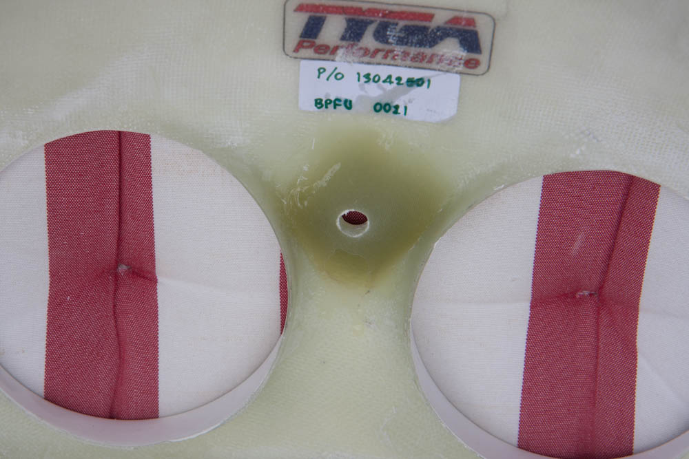
For final fitment, I started by adding a couple plies of BID to the inside of the seat, after sanding it well. The fiberglass job on the fairings would make any Long-Ez builder weep — the top ply of fiberglass is so dry it looks like it’s just glued to the next one. In the corners, there isn’t so much an “air bubble” as the ply being completely lifted from the base, forming a cavity. This isn’t just the old part, the layups on the new front fairings look the same. I realize these aren’t structural parts, but come on…
When attaching things with epoxy, it’s good practice to cut some structure into the surface so the epoxy has something to “bite” into.
To ensure that the point got into the exact right position, I then mounted the fairing by the front holes (the ones that are still there…). I cut some notches into the plug to make it adhere better, scraped a pile of fairly dry flox on top of it, and positioned it into place. Then the fairing was pushed down solidly onto it with some pack straps.
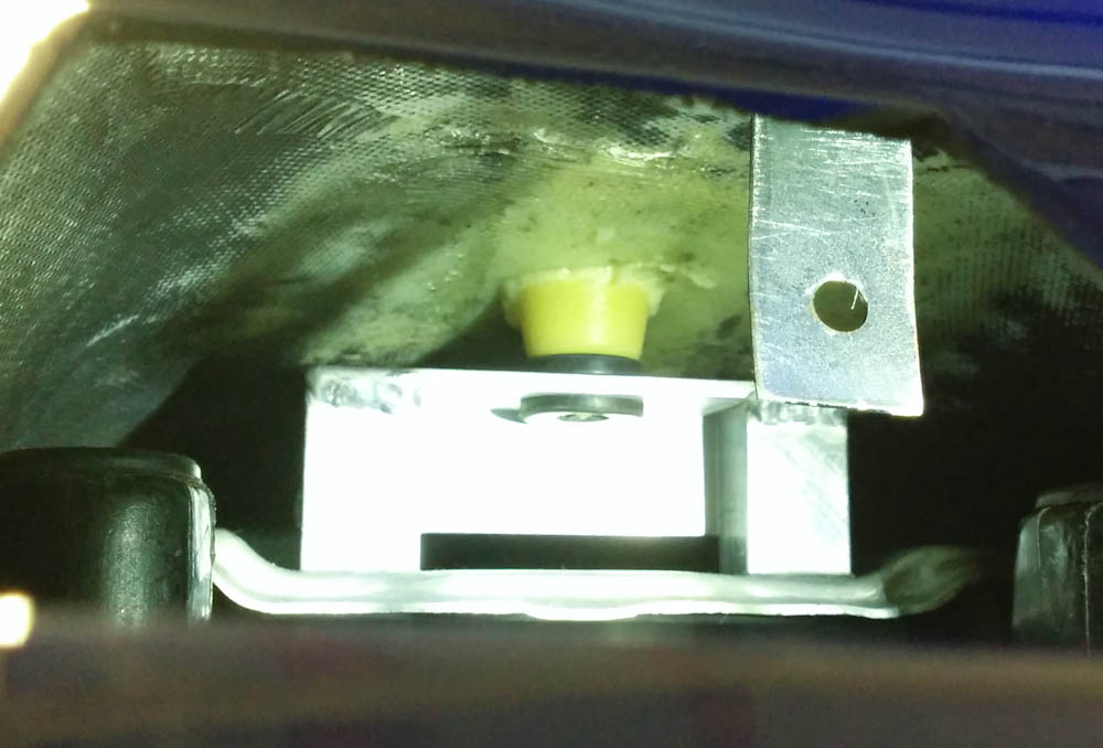
Here’s the point floxed in place against the inside of the fairing. This should securely position the back part of the fairing.
Now that the fairing is securely positioned both front and back, it should be possible to lay out the rear screw holes so that there won’t be any tension when mounted. Stay tuned.
It’s been a while since I wrote something about the bikes. Not much has really happened since we moved to Hilo, but I’m now back to doing some stuff on the NC30. It really started before we moved. I mentioned back in the post that I was going to replace the nonstandard headlight in the Tyga fairing with stock headlights. The impetus for this both that the bike needed to pass the Hawaii vehicle safety inspection and that the stock double round headlights just personify the VFR to me!
New headlights are impossible to get, so I ordered a set of Chinese ones off ebay. Getting a new headlight of course also required getting a new upper fairing. The Tyga fairing has a different shape than the stock one, so the only reasonable replacement was a Tyga “NC30 style” one. After having that delivered from Thailand, I unfortunately discovered that it didn’t fit with my lowers anyway:
This is an example of how the new Tyga upper fairing fit against the old lower one. Not so good.
This is just one example of the fitting problem. The curve around the radiator also had a very different radius to it, so there was no way to get it to line up.
After asking Tyga about it they admitted that their early productions had quite a bit of variability to them and were always sold as matched sets. These days their production is better but it seemed likely the old lower wouldn’t fit. Well, whatever. I ordered a new lower, too, along with the stock fasteners that I also didn’t have.
The result? Better, but not by any means perfect:
The new lower fairing. Note how I had to “adjust” the upper left hole for it to fit.
A big problem with fitting fairings after a bike has gone down is that everything ends up out of alignment. The fairings mount into metal brackets that get bent a bit, and it’s hard to find a reference for where things are supposed to sit. At least the stock lower fairing mounts rigidly into the frame at two points, so that gave me a good starting point.
The upper fairings are attached to the two mirror stays that bend up from the tank and to the headlight bracket in front. These both easily get bent if the bike goes down, but after “adjusting” them a bit I got a reasonable fit. The only problem was that the front screw hole was about 1cm too far forward for the headlight bracket.
Luckily the Tyga fairings are fiberglass, so I could apply some of my airplane-building skills and add more thickness to the fairing in this part.
This is the attachment where the fairing screws into the headlight bracket. By adding a pad of tiny fiberglass layers I could build up the seat to the appropriate thickness and drill it out.
With that along with some spacers in other places, I got the fairings to fit pretty well.
Finally, a reasonable fit for the new upper and lower fairings. Now they just need paint.
This was as far as I got before we moved. The bike’s been rolling around in primer since then. Rather than try to recreate the “Red Bull” theme, I want to repaint it the classic stock paint scheme (It’s called “NH-196”. There’s still a sticker under the seat with that code, so I know that’s what it used to look like.)
The classic “NH-196” VFR paint scheme, stolen from 400greybike.com.
After trolling the internet for the correct Honda paint codes for this scheme, I went to Finishmasters to see if they could get it. No luck, these paint codes were in none of their computers. Presumably they only have paint codes on models that were sold in the U.S.
I did manage to source a set of stickers from “ImageWorks” in the U.K. But I kept getting stumped on the paint. Finally I got it from RS Bike Paint, also in the U.K. They have it in water-based paint, so they could ship to the U.S. (However, they could not ship to Hawaii, so I had to use an intermediary in CA to re-send them in USPS to me.) Now I have all I need to paint.
Before painting, though, there’s a bit more fairing work to be done. I’ll leave that to the next post.
I know there haven’t been a lot of updates recently, I kind of lost momentum on the writeups. However, it’s not that things haven’t been happening. The work on the house continues.
It seems that most of the things we’ve done so far has to do with water. Maybe that’s just how it is living in a place like Hilo. (The weather station says we’ve had a total of 1300mm of rain (yes, that’s 1.3 meters) since it started operating in July.) Or maybe it’s just that whoever built the place didn’t think things through quite all the way…
One thing that has been puzzling me since we moved in is where the downspout on the back side of the house goes. The PVC downspout disappears into an old cast iron pipe with no obvious exit. At some point, I even put the garden hose in it and walked around trying to hear where the water came out, with no luck. Oh well.
Then, a couple of weeks ago, I was out back and realized that this sound I heard that sounded like our gas grill was on wasn’t that at all, but a leak in a cast iron water pipe going into the ground next to the previously mentioned mysterious downspout. Where did this water pipe go?
While we have several taps out in the “orchard”, I know where they are fed from and this wasn’t it. There was no way to turn the water to this pipe off, so I turned off the water to the house, twisted the pipe off with my big-ass pipe wrench (yeah, it was that rusted through) and plugged it. Then I started tracking where it went.
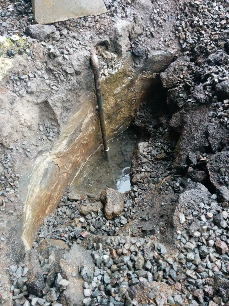
After going out under a concrete step and passing under one of the concrete blocks supporting the lanai (awesome routing…) it made a 90-degree turn down and disappeared into something that looked like a concrete-lined hole. After some amount of digging and lifting out huge chunks of lava (the other constant in yard work here…) I got to a concrete lined bottom where the pipe disappeared down. With standing water in it.
This is the mysterious waterpipe descending into the concrete-lined pit.
Now, while it rains a lot here, you don’t usually find standing water except when it’s raining heavily, because the lava rock is very porous. But this was a concrete lined surface, clearly made to not let water through. And at this point, it hadn’t really rained for a month (we’ve had a very dry “winter”) so that water must really have been sitting there. What in the world…
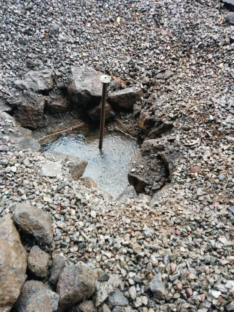
Kathy pointed out that maybe this was connected to the mysterious sprinkler-looking thing coming up in the middle of our gravel-covered backyard. I’d never really thought about it, but this thing looked really out of place given that a) we don’t have sprinklers anywhere else (and this is Hilo, why would you?) and b) if you were going to put in a sprinkler, why put it in the middle of a large gravel-covered surface?
This is the mysterious sprinkler, ascending from the concrete-lined pit. At this point the water level was already rising from the rain.
I started digging down around it, and after a little more rock-lifting, that pipe disappeared under the same concrete-covered surface. Circumstantial evidence, but they sure appeared to be the same pipe. The only problem with this theory is that there was no water coming out of the “sprinkler” and I saw no obvious shutoff between it and where the pipe attached to the house water supply. I guess it’s possible the pipe was completely plugged with gunk somewhere, but that can’t always have been the case, can it? Mysterious.
I proceeded to follow the edge of the concrete-lined surface, tracing out a large, irregular hemisphere centered on the “sprinkler”. It almost looked like there once upon a time had been a pool in the backyard, that then had been filled in with rocks.
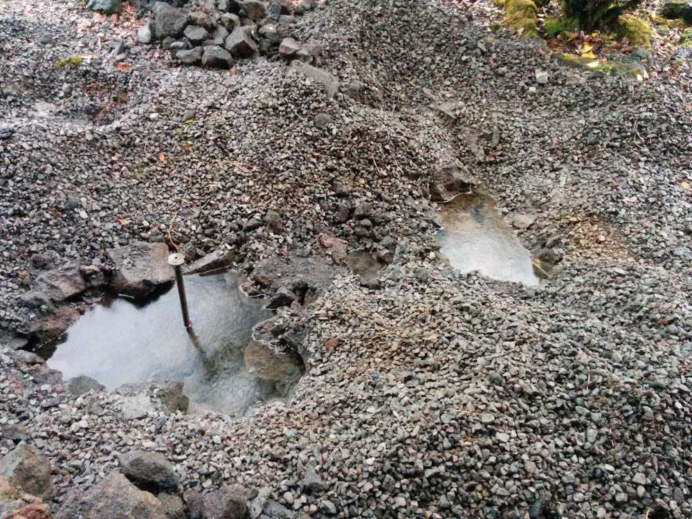
At this point of the exploration it had serendipitously started raining… It now became clear where the mysterious downspout ended up. The cast iron pipe ended at the edge of the “pool” (it’s kind of visible to the right of where the water pipe comes out in the first picture) and was dumping a steady stream of rainwater into it. Over the next day we got about 130mm (5 inches) of rain, after which the “pool” looked like this:
After 5″ of water in 24 hours, the concrete-lined pit was filled to the rim with water.
Yep, that’s right. The entire, 15-foot diameter “pool” is now filled to the rim with water. Right next to the house… What an awesome idea. Luckily it looks like the pool actually is sealed enough that it does not leak out water towards the house. I dug an “exploratory well” on the house side of it and it remained dry down below the surface. But still.
At this point our theory is that the house originally had a Koi Pond. They are quite popular here with Japanese owners. The lanai is a later addition, so when they added that, I guess they just filled the pond with rocks and covered the area with gravel.
Now, I’m not psyched about having all this water near the house, so my plan is to crack a hole in the pond at the bottom away from the house and then run a pipe down to the lava wall in that direction and dump the water out there. That way there should be no chance of having this water end up anywhere near the foundation of the house. It’ll take quite a lot of digging to get a pipe down to that level, though.
I’ve been thinking of getting a welder for a while now, it seems like one of these “generally useful” things. Finally, I bit the bullet, read a bunch of online reviews, and ordered an AlphaTig 200X TIG welder. This is pretty much the cheapest TIG welder you can get that can weld Aluminum, and while it may be cheap, it’s a capable machine.
While I had MIG welded a bit way back when I used to work summers at my Dad’s work at Birstaverken, I’d never used TIG before. TIG isn’t exactly the easiest or fastest way to weld, but the ulterior motive is that if any welding’s going to be useful for airplane work, it’ll be TIG. There are a bunch of useful videos on youtube, like the “Mr TIG” series and this guy’s videos.
Apart from there being a bunch of terminology to learn, you also need Argon. Predictably, Argon in Hawaii is a scarce resource and a good-sized bottle runs over $200 for a fill. Then you need the bottle, of course, which was about $250 alone. The cost of the welder may actually not be the largest part in this hobby…
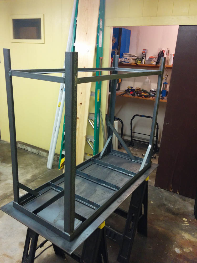
Anyway, the first obstacle anyone learning to weld encounters is that you need something to weld on. While I have a few workbenches, none are made out of metal so they can’t really handle the heat of being welded on. Well, what better way to get started than to weld up my own table? I found the local steel yard and picked up some angle iron and a 1/4″ plate for the top.
Here, the table is almost complete, and the top is being welded to the frame.
The other thing you need to do if you want to work with metal is cut it. Using a hack saw and angle grinder wouldn’t quite do it at this scale, so I invested in an Evolution Rage mitre saw that can cut anything from wood to steel. The cut is very clean and with a little care the angle can be adjusted to make very square cuts.
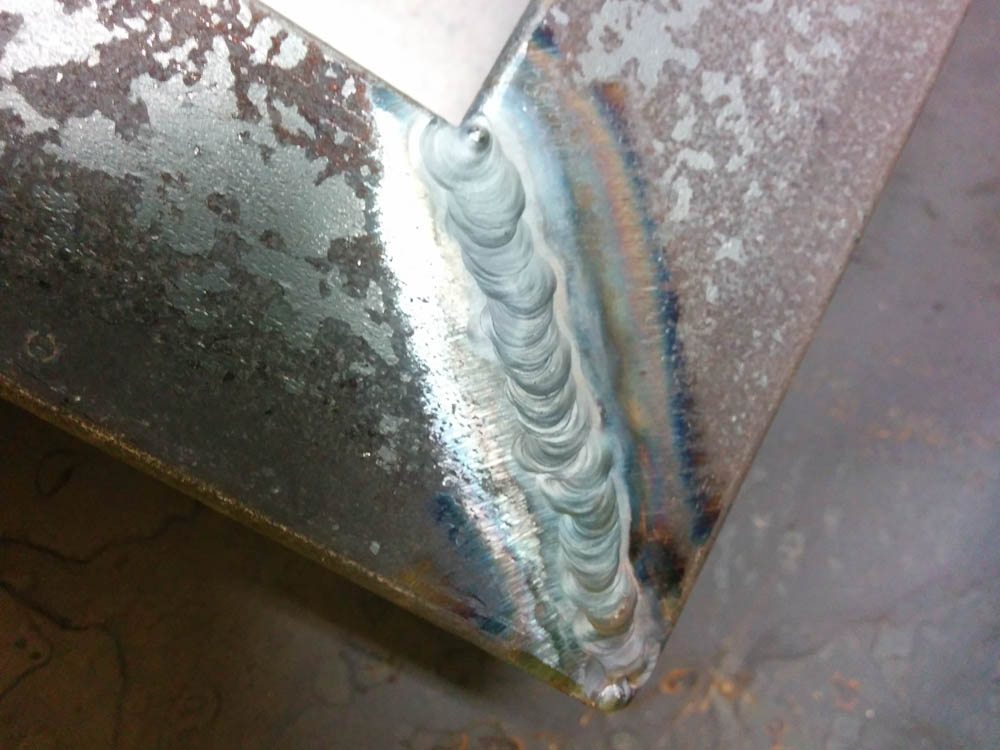
Anyway, I can’t say the welds were all pretty, especially inside corner and butt joints were a challenge. But the table came together and serves its purpose!
The welds don’t look too bad. I’m not showing the butt joints, though!
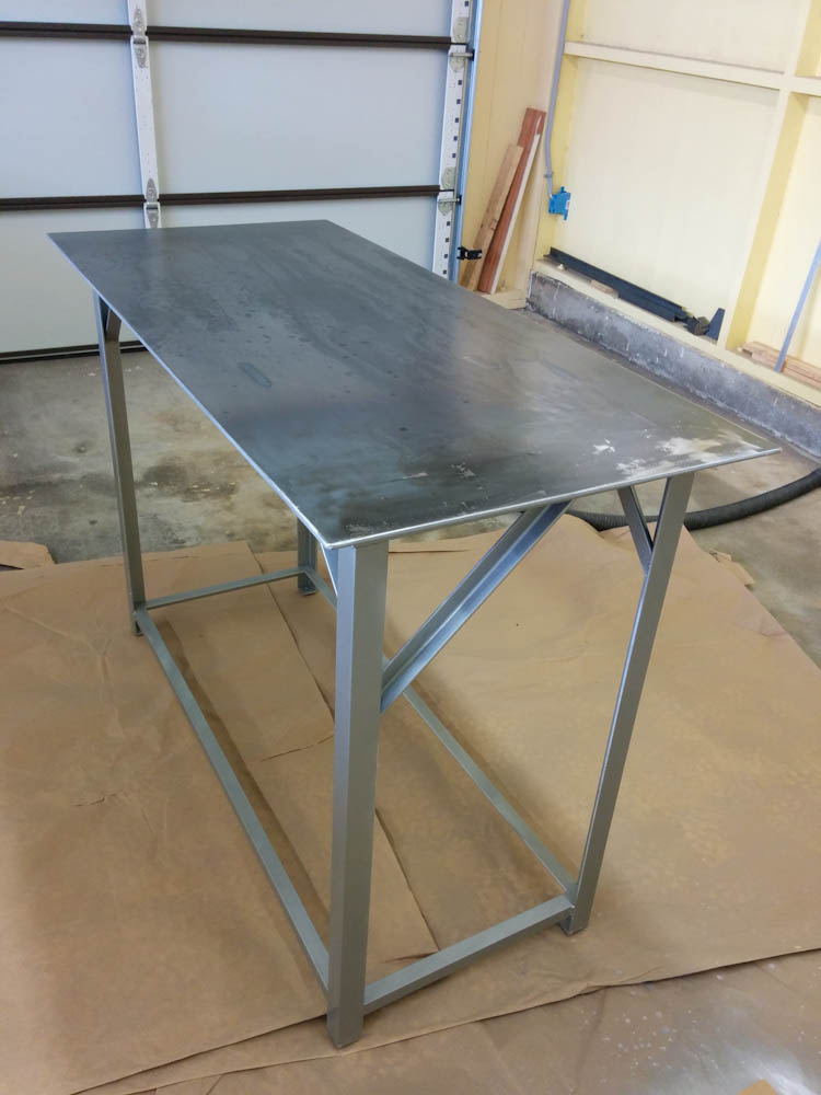
The final product, with paint. The top is not painted since it needs to be conductive.
My next welding project is going to be a rack for parts storage, in Aluminum. More on that later.
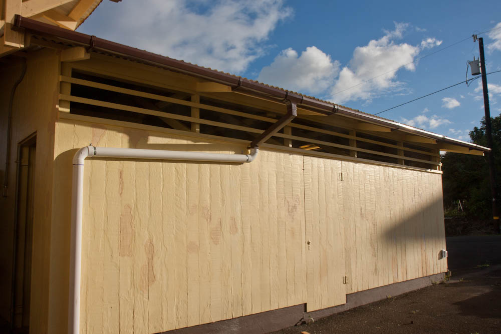
Another not-so-exciting improvement accomplished while my Dad was here was the replacement of the old gutters on the garage. They were of the semicylindrical, thin-metal kind and were sagging and leaking in several places. The metal itself was sufficiently corroded that replacing the whole thing seemed like the best option. (Not to mention that we were unable to find spare parts anywhere.) Gutters these days are overwhelmingly vinyl, and the brown option kind of match the brown on the house pretty well.
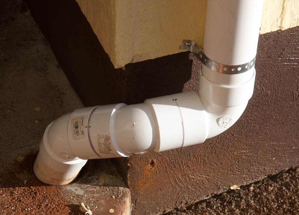
The new gutters. Instead of the cast-iron pipe the old ones discharged into, we mounted a 3″ PVC pipe along the wall.
We also took the opportunity to replace the cast-iron riser that came 7 ft out of the concrete and probably weighed 150 pounds. We just cut it with the angle grinder and routed the new PVC pipe into the hole.
This isn’t exactly pretty but routing the pipe around the corner and into the hole where the old pipe ran wasn’t trivial.
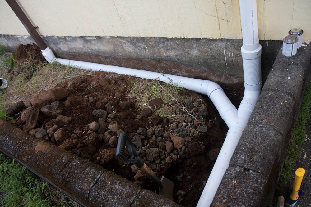
Finally, the discharge on the other side was improved. There used to be two PVC pipes (the one from garage roof and also one from one side of the addition) terminating about 2ft up the garage wall here, dumping the water into the planter bed. During moderately heavy rainfall, the planter bed would turn into a pool. Since you don’t really want standing water against the concrete, we extended the pipe all the way down through the planter bed and through the outside. Now the water dumps into the gravel there, but we have the option of hooking it up to the drain pipe from the driveway, when I get around to adding that.
The drains from the garage (on the left) and the roof over the addition now go into a pipe and out through the wall of the planter box.
There’s something strangely satisfying about building water transport systems. (And there’s a lot of opportunity for that living in Hilo…) I guess it’s like the grown-up version of building dams in ditches. (Everyone did that as a kid, right?)
The house apparently never had a range hood. As someone who’d never seen a kitchen without a range hood until I moved to the U.S., this baffles me. Like there isn’t enough grease and crap that coats everything in the kitchen even with one. In any case, it had been on our list to install since moving in, and we even bought a Vent-A-Hood some time last spring. But since hooking it up involves cutting a hole in the wall of the house, I hadn’t quite worked up the courage to do it. My Dad however, had no such problems!
When my parents visited in October, one of the first things he wanted to do was install the range hood. Since it’s a single wall house, getting through the wall isn’t exactly difficult. A few pilot holes and the jig saw accomplished the job quickly.
Here’s Bengt and the hole in the wall for the range hood vent.
The hood just screws into the bottom of the cabinet, into which we had to cut a hole for the vent. But then a small complication arose: we’ve been wanting to strip the lead paint from the cabinets, and this wouldn’t be very easy after installing the hood. Thus, we decided to strip the old and add the new paint before mounting it. Because of drying time, that added two days to the project. It’s not exactly show room quality, but who’s going to look in the cabinet where the vent hood duct is located anyway?
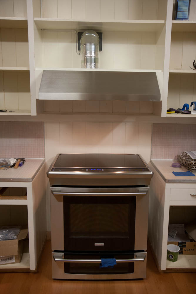
The final product looks like this:
The final vent hood installation. It matches the range quite well.
Note the small cover pieces on each side of the hood. Since the hood is about 4″ narrower than the cabinet above, there would be narrow openings here. This was unacceptable to Bengt, so he manufactured cover pieces to go on the front and around the bottom of the hood. It looks much better, and it also prevents grease and crap from getting into that hard-to-clean space.
While the range was pulled out, we also took the opportunity to finally move the 50 amp outlet, which was mounted too high on the wall. There is a slot at the bottom of the range, but the outlet was about 1″ too high. Tilting it 90 degrees solved that problem, so now the range can also be slid in so it’s flush with the counter… or at least it will be once we’ve covered up the empty spaces on each side. That will have to wait for new counters.
So how is the Vent-A-Hood? It was quite expensive, but is it worth it? Yes. I’m intensely annoyed by loud kitchen fans, and it’s indeed quite quiet. It’s not quite at the level of my parents’ vent hood (which I think is an Electrolux) but it’s by far the most quiet I’ve used in the U.S.
We were initially disappointed, though, because it seemed really loud and didn’t even suck that well. After a week or so, I took the cover off and realized what the problem was. Apart from the big “flap” on the vent on the outer wall (the kind which is blown open by the outgoing air) there is a smaller, similar one on the inside at the perimeter of the centrifugal blower. This flap, which is on the removable cover, had been pinched against the mount and couldn’t open. So the blower was just sending the air spinning and it had nowhere to go!
Once this was rectified, the volume dropped significantly and the sound changed from “choked” to “free flowing”. Not only that, the air flow also increased a lot — before, the flap on the outside barely opened when the fan was running on full. Now it’s fully open even on the lowest setting!
So it’s good — but if you get one, beware of this little gotcha.
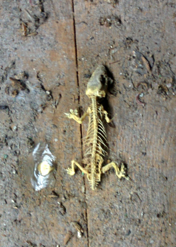
Oh, a bonus story: While crawling around in the attic for this project, I came across this perfectly preserved Gecko skeleton:
While crawling around the attic, I came across this. Yep, that is a perfectly preserved Gecko skeleton.
It’s been a while since the last update, where we had started to demolish the next room, but it is not for lack of activity.
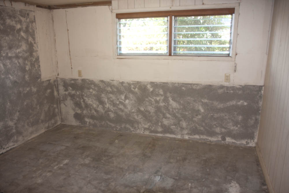
The next basement room, with the bare concrete floor mostly ground clean.
The concrete floor has been ground using the same machine from Home Depot that we used in the previous room. This floor was in better shape in that it’s not crumbling like the other one did, but on the other hand it was quite uneven. Also, we need to get the old white paint off the concrete wall since it’s bubbling due to the efflorescence. This has meant quite an investment of time with an angle grinder and a diamond grinding disk.
The kitchen floor still needs to be ground down, but it’s a pretty small area:
The kitchen floor after ripping out the old linoleum. This is before any grinding.
The big uncertainty at this point is that there are a few spots along the internal concrete “wall” (it’s only an inch or two high) where moisture seems to be wicking up through the cracks where the carpet was nailed down. There are also a few areas on the concrete wall towards the front stairs that have visible moisture. This is not old moisture trapped in the concrete, because it gets more intense if the weather has been wet.
The cracks where the carpet nails went are visibly damp.
It’s very puzzling. My hypothesis is that this “wall” was put in before the floor (recall that the basement originally had a dirt floor) since it’s supporting vertical loads. If so, it probably goes all the way down to some solid rock. If there’s still moisture coming down under the house (the French drain doesn’t extend to under the stairs and towards the driveway) it would get trapped by this wall and then wick up through the concrete.
It’s hard to say without testing, which would require knocking a big hole in the floor and digging down to see what’s happening. Not an attractive prospect.
I said I would do a little writeup of the software for the weather station earlier, and I realized that it would actually be good to do a little How-To about using an Xbee to wirelessly upload now software to an Arduino. While I’ll include a bit of explanation along the way, there will be (I hope) complete instructions for getting an Arduino Pro Mini working with wireless bootloading. Because I use Linux, that’s what I’ll describe. I also don’t use the Arduino IDE, preferring Emacs and GNU Make since that’s what I use for work and my other programming projects.
Background
The idea is that once you’ve gone wireless and have an Arduino hooked up to an Xbee somewhere, it’s a big inconvenience to have to hook it up to a USB cable every time you want to update the software its running. Since Xbees can act as a serial pipe, it should in principle be possible to just do the upload over that link, but in practice the default bootloader is not very robust to lossy radio links.
When I first tried to do this back in 2009, I came across this tutorial by Nate at Sparkfun. He wrote an alternative bootloader called sfxb (for SparkFun XBee, I assume) which checksums the uploaded data and can request retransmissions of bad packets. This way a few lost packets won’t kill the upload. The big drawback, at least for me, was that his uploader only worked for Windows.
Luckily another user, Alan Backlund, posted in a comment to the tutorial that he had added the upload protocol to avrdude, the normal program for programming AVR microcontrollers. You can easily compile this on Linux or Mac. I used his code for a while and it worked fairly well. I also tweaked the bootloader a bit to make it more robust.
Eventually I wanted to use Series 2 XBees. Series 1 XBees can be programmed to automatically pass digital lines, which means you can easily pass the Arduino reset line over the radio link, but Series 2 ones don’t do this. I also wanted to use the XBee in API mode, where you send explicit packets instead of just passing serial data. This is necessary if you want your XBee to talk to more than one remote node, since otherwise you can’t know where the data is coming from. This required a more extensive rewrite of the avrdude sfxb programmer. (If you want to learn more about how XBees work and how they can be used to make a distributed network for small amounts of data, the book “Building Wireless Sensor Networks” by Robert Faludi is a good start.)
At this point, I have a pretty well set up system that I’m using to have my Linux server get sensor data from 3 different remote XBees. Using my software, I can also upload new code to one remote Arduino without disturbing the links to the others. I’m pretty happy with the setup and I figure it can be used fruitfully by others, so I figured I should write a detailed description with links to the code.
So, if you’re interested in uploading code to an Arduino over an XBee link and in general interfacing with multiple remote XBees, read on. This is going to be a pretty long and detailed post, but I hope by the end of it you’ll at least be able to get your code uploaded. The rest of the code may have to wait for another post.
Overview of Atmega bootloading – Fuses and Self-programming
There are two different ways of writing programs to the flash memory inside an ATmega chip.
The first is to write data directly to the memory, normally using the SPI serial bus. If the reset and SPI clock pins are held low when the device is powered up, a special instruction sent over the SPI bus will make the device enter programming mode, where data sent over the SPI bus gets written directly to the flash memory.
The second method is by “self-programming”, where the processor executes a program that writes data to its own memory. The flash memory on the Atmega 328P is divided into two different areas: the boot loader section and the application section. Code executing in the boot loader section can issue programming instructions that write data to the application section, but the boot loading section can only be modified by the first method: direct programming over the SPI bus. The size of the boot loading section can be set using programmable fuse bits to anything from zero to 4096 bytes. The remaining part of the 32K flash memory is available for applications.
A boot loader is a program that resides in the boot loading section which reads data in some way (normally over the serial connections) and writes it to the application section. The boot loader is entered automatically when the device is powered up or reset. If it detects incoming data, it proceeds to read it and write to the flash memory. If there is no incoming data it just jumps to the application section and starts the normal program.
Chapter 23–25 of the datasheet describes all the details of how self-programming or external programming works. If you want to learn the details, I encourage you to read them carefully.
Installing the bootloader
From the above, it’s clear that the normal way Arduino programs are uploaded to the chip can not be used to update the bootloader — the bootloader cannot change its own code since it’s located in the boot loading section. (And even if it could, it would overwrite itself part way through.) The bootloader must be programmed using the SPI bus (the 6 “ICSP” pins on a standard Arduino footprint used for this are nothing more than the SPI, reset, and power pins.)
To write the programming instructions, you need an external “programmer” to handle the SPI communication. I use Sparkfun’s “Pocket AVR programmer”, which is just an ATtiny microcontroller programmed to interface between the USB port and the SPI bus. It’s only $15 and has been totally reliable for me.
In principle you should be able to write an Arduino program yourself to write the SPI instructions yourself, which might be a fun project if you really want to learn how it works. Sparkfun has an article about programming bootloaders, too.
Step 1: Hooking up the Arduino
Now let’s get practical! The Arduino Pro Mini is a low-cost Arduino clone from Sparkfun. Because it’s just a bare board, it’s much cheaper than a normal Arduino, but it also means you need to set some stuff up to be able to use it. It’s perfect for embedded projects where you need an Arduino to control something in a permanent installation. It’s what I used for the Weatherstation and in my (yet-to-be-described) project to talk to the inverter for our solar system. Sparkfun has a tutorial describing how to set it up. It comes in 3.3V and 5V versions, and the 3.3V is good for hooking up to an XBee since those run at 3.3V, too.
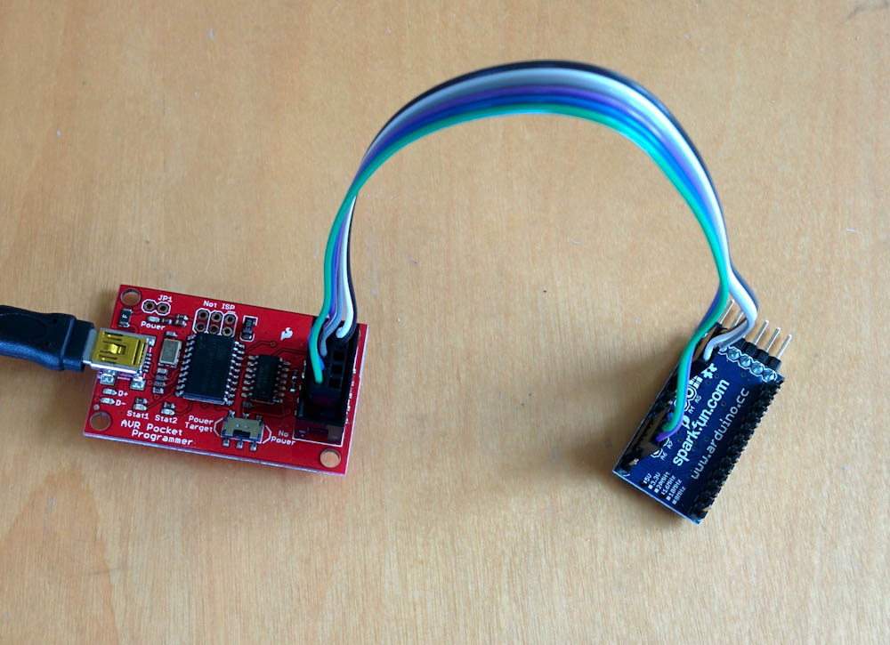
The first thing to do, after soldering some headers to the Pro Mini, is to hook it up to the AVR programmer so we can upload the bootloader to it. This involves connecting 6 wires, VCC, GND, reset, and the 3 SPI pins: MOSI, MISO, and SCK. The pins are clearly labeled on the back of the connector for the programmer. For hooking them up to the Arduino, I made a little wire myself so I don’t have to figure out which pins are which every time, but you can also use breadboard wires.
The Arduino Pro Mini on the right, hooked up to the “Pocket Programmer” on the left.
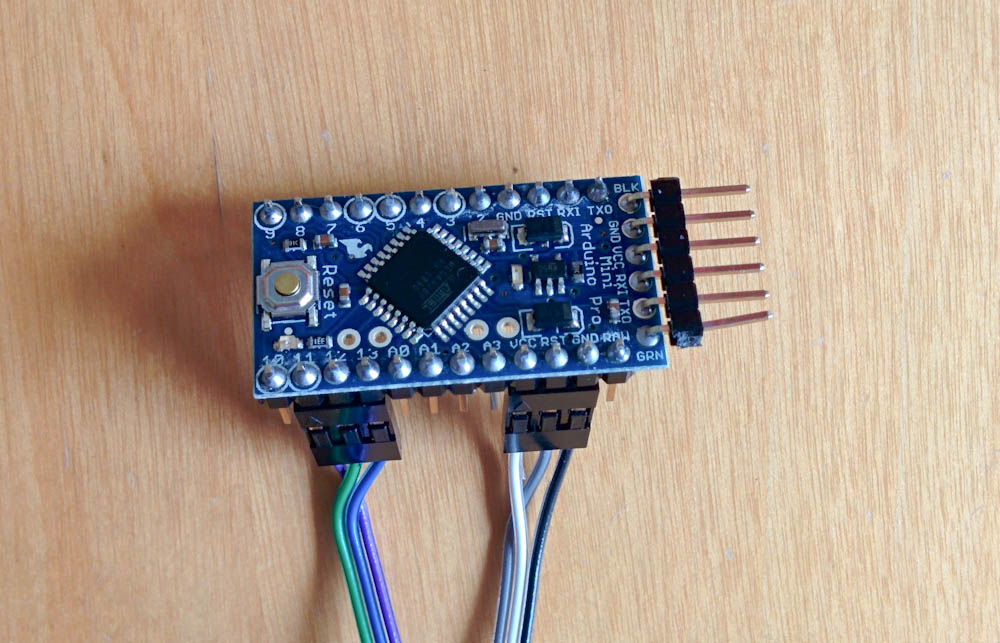
The six pins on the programmer connect to the Arduino in two groups of three, one for power/reset and one for the SPI pins. The picture below shows which are which.
This shows the six pins that are connected to the bootloader. The thee on the right are VCC, GND, and reset. The three on the left are the SPI pins: MOSI (pin 11), MISO (pin 12) and SCK (pin 13).
Once it’s hooked up, the red power LED on the Arduino board should light up if you plug the programmer into a USB port.
Step 2: Setting up the avr build environment
In order to be able to compile Arduino programs, we need to set the build environment up first.
Depending on your system, this might require some fiddling, but the good news is that you only have to do this once.
The first step is to install the avr-gcc toolchain so you can compile AVR code. Depending on your Linux distribution, there are probably packages for avr-gcc and avr-libc. (If there isn’t, you have to build them yourself, which is beyond the scope of this tutorial.) Once you have these installed, you should be able to type avr-gcc --version in a shell and see the gcc print out its version. On my machine, it responds avr-gcc (Fedora 4.6.2-1.fc16) 4.6.2
Once this works, you need to download and build avrdude. This will be used to program the bootloader onto the Arduino but also to upload the programs over the XBee once we’re done with all of this.
Programming the bootloader can be done with the normal avrdude but since you’ll need the version with the sfxb bootloader to actually upload programs later, you might as well get it compiled right now. You get it from my Bitbucket repository by doing git clone git@bitbucket.org:lutorm/avrdude.git.
Building and installing avrdude is done with the GNU autotools, if you’ve ever compiled code on Unix you’ve probably run across it before. The file INSTALL has instructions, but briefly they consist of doing ./configure --prefix=$HOME
make install
If all goes as planned, this will install avrdude in the bin directory under your home directory. (Omitting the –prefix argument from configure will make it want to install it in the system-wide /usr/local directory. I keep it in my home dir. Then add $HOME/bin to your PATH variable so the shell will find it.
If avrdude doesn’t build properly, you’ll have to figure out why. There shouldn’t be any problems, but sometimes if there are it’s probably because your system has some file in a slightly different place.
Step 3: Compiling the bootloader
Once avrdude works, it’s time to download the sfxb bootloader. You can get it (and all my other Arduino code) from by Bitbucket repository by doing git clone git@bitbucket.org:lutorm/arduino.git. In the arduino directory you’ll find a directory called “sfxb_bootloader”. Go there.
The directory contains two files, the Makefile and sfxb_bootloader.c. There are a few things you need to make sure are set up correctly before compiling the code.
The first is the clock frequency of the Arduino: By default, the code is set up for the 8MHz 3.3V Arduinos, but if your clock speed is different, you need to change this line in the Makefile: F_CPU = 8000000 and this line in the bootloader source: #define CPU_SPEED 8000000LL so they reflect your processor speed. If your Arduino doesn’t use an ATMega328P, you’ll also have to change the MCU line.
The third thing that may have to be adjusted is the LDSECTION line. This determines where in memory the bootloader will be located. The value in my code is byte address 0x7c00, which is appropriate for a 512-word boot loader size (see Table 24.8.16 in the datasheet.) The sfxb bootloader code just barely fits inside of this, so if you add anything to it, you’ll likely have to increase the size of the boot leader section to 1024 words, costing you 1K bytes of program space.
The stock Arduino bootloader is bigger than this, so Arduinos generally do not come programmed with a 512-word boot loader size. This corresponds to fuse values BOOTSZ0=0, BOOTSZ1=1. Before we can program the bootloader, we have to adjust the fuse bits to set the BOOTSZ bits correctly. If this isn’t done, the Arduino will jump to the wrong address when it boots, and will either start in the middle of the bootloader or into the application code. The result will be that the bootloader may appear to work initially, but will either not write to memory correctly or will cease to work after code is uploaded to the boot address.
There is a handy fuse calculator at engbedded.com that can help you interpret the fuse values. To read the current fuse values with avrdude, do
avrdude -c usbtiny -p atmega328p -U lfuse:r:-:h
(If you don’t use the pocket programmer, you have to change usbtiny to whatever is appropriate for your programmer. If it doesn’t work, it’s also possible you’ve hooked up the Arduino to the programmer incorrectly. Double-check the connections.)
The command should have spit out the current value of the lfuse bits in hex to the screen, along with some diagnostics. Do the same with hfuse and efuse and use the fuse calculator to see what fuse bits this corresponds to. The BOOTSZ fuse bits are in hfuse. Set those to the values above and see what fuse value this corresponds to. For my Arduino Pro Mini, the correct hfuse value is 0xdc. This corresponds to BOOTRST programmed (which means the Arduino will jump to the boot loader at reset) and SPIEN programmed (which enables SPI programming) along with the correct size boot loader section. Now write the fuse value to the Arduino by doing
A word of caution: It is possible to make the Arduino unusable by writing the wrong fuse bits. For example, if you clear the SPIEN fuse bit, you can no longer program it using the serial programmer. Changing the clock values in the lfuse to something incorrect can also make it not run. I think there are ways to fix this, but you may not have the equipment to do it, so be careful. Double-check the command before writing the fuse bits to make sure you’re writing the correct value to the correct fuse byte.
We are now just one step away from programming the bootloader. Go to the sfxb_bootloader directory in my arduino repo and do make. Hopefully this completes without error. Now do make program_serial. If it’s all hooked up correctly, the LEDs on the programmer should start blinking like crazy and avrdude should show the progress first uploading and then verifying the program being written.
Once avrdude is done, you should see the LED on the Arduino double-blink every couple of seconds. The double blink is the sign that the bootloader is running, and since there is no other code on the Arduino, it’ll just run over and over again. Once you get to this point, the hardest part is over!
I made a short video showing how the upload and the boot loader is supposed to work:
The sfxb protocol
Now that the bootloader is written to the Arduino, what do we need to do to upload code to it?
The first thing the bootloader does, as we saw in the video, is blink the LED twice. After that it sends a single character 0x05 over the serial port and waits for a response. If it gets a character 0x06 as response, it starts waiting for a new program to be uploaded. If anything but a 0x06 is received, or if nothing is received for a certain time (currently programmed to be 300 character periods), it jumps to the start of the application section and starts the normal program.
Uploading a new program happens in chunks. For each chunk, the bootloader sends the character ‘T’, meaning it’s ready for a transfer, and waits for a response consisting of a ‘:’, the number of bytes in the chunk (as a byte), the 16-bit address of the start of the chunk, and an 8-bit checksum of the following data. It then waits for the announced number of bytes of data to be received.
After the chunk is received, the data is compared against the checksum, and if it passes, the data is written to the flash and the LED flashed briefly. If the checksum test failed, it responds with a character 0x07, meaning the uploader needs to repeat the chunk (and double-flashes the LED), otherwise it sends a ‘T’ and the process starts over with the next chunk.
The end of the upload is signaled by sending the character ‘S’ as the size of the next chunk, the receipt of which makes the bootloader exit flash programming mode and jump to the start of the freshly-downloaded program.
This is a pretty simple scheme, but has proven to be quite robust. If data is corrupted in transmission, the bootloader will just ask for a repeat of the data over and over again until it gets a correct chunk. It might take a while, but eventually the data should get across. The only time-sensitive part of the negotiation is that the initial exchange of 0x05/0x06 has to be received by the bootloader before it starts the normal program.
Step 4: Setting up the XBees
Ok, so now that we know how the bootloader works, what do we need to do to get this working using XBees? I’m going to assume you know how to configure the XBees (or know how to google for it.) There are only a few things to make sure:
While so far everything we’ve done is agnostic about how you hook the Arduino up, the avrdude uploader that we will use only works with Series 2 XBees. (I suspect it wouldn’t be that hard to get it to work with Series 1 as well, but I don’t use them.)
The remote XBee (the one hooked up to the Arduino), must use AT (not API) firmware. It can use either “Router” or “End device” firmware. (A router will pass messages to other XBees, but an end device will use quite a bit less power. Unless you have a power constraint, make it a router.) It must also be configured for 19200 baud, because that’s the speed the bootloader uses to talk over the serial port. (The only way I know to update the firmware is to use X-CTU on a Windows machine, if you don’t have a Windows machine you need to figure out a different way of doing this.)
While in X-CTU (or however you are configuring the XBees), write down the 64-bit address of the remote XBee (commands SL and SH). You need this address so you can tell avrdude where to send the upload in Step 5.
All XBees must obviously be set up to use the same PAN ID, otherwise they won’t talk to each other.
The reset pin on the Arduino must be hooked up to the DIO3 pin on the remote XBee. You don’t need a capacitor on the line, but it doesn’t hurt either.
The local XBee (the one hooked up to whatever is going to be sending the programs) must use “Coordinator” API firmware. It can be configured at whatever speed you want, but I use 57600 so that’s what my Makefiles are set for.
Make sure any XBees with router firmware are set with JV=1. (This means that whenever they are powered on, they will search for a coordinator. If you leave this at 0, they will remember the channel they found the coordinator on last time, so if the coordinator is ever restarted, they won’t find it at its new channel.)
If you read the SparkFun tutorial I linked to at the beginning of this page, you might have noticed that what they did was connect the DIO3 pin on the local XBee to the RTS pin on whatever you use to connect the XBee to a USB or serial port. This works because Series 1 XBees (which that tutorial used) can use the digital input/outputs to pass binary signals. If the input pin goes low on one radio, it’ll send a command to the other one to set the pin low. That way you can “pretend” that the reset line on the Arduino is connected directly to the RTS pin, which is how an Arduino is “normally” reset when you upload a new program using a USB cable.
The Series 2 XBees, however, do not have this binary line passing capability, so to reset the remote Arduino we’re going to have to send explicit commands to bring the DIO3 pin low and then high to start the bootloader. Avrdude does this for us.
Avrdude and the sfxb programmer
We are finally at the point where we can try uploading a program to the Arduino. While you can compile and invoke avrdude any way you want, this will describe doing it with the Makefiles I’ve set up for my projects.
Step 5: Uploading a program
For the purpose of this tutorial, let’s upload my project called “boiler_logger” to the Arduino. What it does isn’t really relevant right now, but it’ll serve as a test that everything works.
Go to that directory in the checkout of my Arduino repo. The Makefile in that directory looks like this:
TARGET = boiler_logger

ARDUINO_LIBS = OneWire OneWiretemp memory version XBee PID float16 serial_data
The two first options specify the names of the resulting files and which libraries (under the libraries directory) that should be compiled along with the program. The next options are the customary specifications of which microcontroller and which clock frequency the target is for. ARDUINO_PORT specifies the serial port the local XBee is attached to. On Linux, if you use an FTDI USB adapter, this will be something like /dev/ttyUSB0 which is the default selection. On a Mac, it’ll likely be something like /dev/tty.usb-blahblahblah, which is the second, commented out option. The AVRDUDE_ARD_PROGRAMMER specifies we want to use the sfxb bootloader and that the local XBee is running API firmware. The AVRDUDE_ARD_BAUDRATE should be set to the baud rate of the local XBee.
The interesting option is AVRDUDE_EXTRA_OPTS, which passes arbitrary extra options to avrdude. The -x dest=0x0013a200409eda5b specifies the 64-bit hex address of the remote XBee. Since avrdude must generate API commands addressed to the remote XBee to send data to it, it needs to know this address.
You should now change the F_CPU to the clock speed of your Arduino and set the destination address to the 64-bit address of your remote XBee that you wrote down in the previous step.
Once that is done, do “make” and if there are no errors, “make upload”. Avrdude should send commands to reset the Arduino, and if the handshake succeeds, you should then start seeing messages like “device successfully acked page xxxx”.
If the upload is successful, the Arduino should now start sending stuff back over the XBee, so if you open the /dev/ttyUSB or whatever port the local XBee is connected to and hit the reset button on the Arduino, you should see the message “Patrik’s boiler logger booting …” and then it’ll probably complain about a bunch of stuff… whatever, that means it’s all working and you’re now good to start uploading your own code!
Troubleshooting
If you’ve followed these instructions exactly, there really shouldn’t be any problem, but if it doesn’t work, here are some things to check:
Does the Arduino reset when you start avrdude? You should see the LED double-blink right away when you give the command. If not, either you didn’t wire the reset up to DIO3 or it’s not getting the reset command. Try measuring the DIO3 pin on the XBee and make sure it toggles. You can also hook the remote XBee up directly to the serial port and give it the manual commands to toggle the pin (“ATD3 4” followed by “ATD3 5”) and make sure that resets the Arduino. (Remember the remote XBee should be set for 19200 baud.)
If the Arduino resets, but avrdude says that it got something but 0x05, that likely indicates that the Arduino bootloader wasn’t compiled with the correct F_CPU/CPU_SPEED. You should be able to plug the Arduino in directly to your serial port and see it send an endless stream of 0x05’s at 19200 baud. If not, go back and double check the settings you used when you compiled the bootloader.
If the upload starts but hangs with repeated “device requests retransmission of page xxxx”, the radio link may be too bad. When starting out, keep the XBees near each other to eliminate any reception problem.
If the upload appears to complete correctly, but the Arduino keeps running the endless bootloader anyway (LED double-blinking every 2 seconds or so), the bootloader likely couldn’t write to the memory. Try plugging the Arduino back into the serial programmer and read back the contents of the flash mem with avrdude using avrdude -c usbtiny -p atmega328p -U flash:r:flash.hex:i and see what the memory looks like. If the beginning of the file is all FF’s until you get to the bootloader at word address 0x3e00, the bootloader wasn’t allowed to write to the flash mem. This indicates that either the fuses aren’t set correctly, or the LDSECTION was set incorrectly in the Makefile for the bootloader. You’ll have to start over and double check those.
If the upload succeeds the first time, but not on subsequent attempts (and there’s no double-blink when you reset the Arduino), this indicates the boot reset vector was overwritten with application code. The can be caused by the same errors as the previous symptom.
So that’s pretty much it. If you’ve stayed with me this far, I hope you’re now set up for wireless bootloading. Like I said at the beginning, I’ve found this to be super useful and hopefully it’ll be as useful for others. When I get time, I’ll write a second part describing the Python code I’ve written to communicate with the individual remote XBees. This code is built on top of the python-xbee module and generates “virtual serial ports” for each of the remote XBees so you can talk to them independently. But this writeup is long enough already.
If you have any questions, or if you find any bugs in the bootloader or avrdude code, please send me an email at code@familjenjonsson.org. Happy uploading!
In the previous post I talked about making the antenna for the weather station. Now, what’s that antenna connected to?
An XBee-only solution?
The initial iteration, that I talked about in the first post, was to just hook up analog humidity and temperature sensors to the XBee’s analog inputs. However, I had trouble getting the readings to be reliable. Even after adding an opamp buffer to the humidity sensor output, it would show weird shifts where the reading would look OK for several hours and then, all of a sudden, drop by tens of percent.
The other problem was that I wanted to add more sensors, like pressure and light, that only were available with I2C connections. I2C is a simple digital communications bus that uses two wires, clock and data. The XBee can’t speak I2C, but you can emulate it by sending commands to switch the digital outputs and read the digital inputs. I wrote some Python code that would talk I2C through the Xbee in this way, and it actually worked. The problem is that it’s agonizingly slow. A common speed for real I2C connections is 100kHz, with the Xbee I managed at best 5Hz! At that rate, it took 30s just to measure the light from the TSL2561 light meter I got. Apart from taking forever, this would also totally kill the battery life, because the Xbee not only would have to be awake but even be transmitting and receiving constantly. While an idle XBee uses 15mA, an XBee with the receiver on uses at least 35mA. This solution was not acceptable.
An Arduino+XBee solution?
If we instead offloaded all the measurement functionality onto an Arduino, we could let the XBee sleep for most of the time. A sleeping XBee uses less than 1uA (that’s micro amp), so that would save a bunch of power. Of course, instead we’d need to power an ATmega 328, but an active ATmega 328 running at 3.3V, 8MHz, only uses about 4mA, and it can quickly go idle and only use less than 1mA. From a power consumption standpoint, this is a far superior alternative.
Further advantages are that an Arduino talks I2C natively, so talking to I2C sensors is quick (and reliable), and things like the wind meter, which requires measuring how many times per second it closes its switch, can be done efficiently by letting the microcontroller sleep for most of the time.
Finally, a reliable I2C connection meant that I could get rid of most of the flaky analog sensors and not have to worry about analog noise, buffering the sensor outputs, etc. On top of that, I’d already bought a few 3.3V Arduino Pro Minis from Sparkfun for $9 when they were on sale. This was the way to go!
Sensor inputs
Now that I could easily interface with many different sensors, I could go to town. These are the sensors I used:
Temperature and humidity, using an HTU21D I2C sensor.
Rain and wind with Sparkfun’s weather meter kit. The rain is measured by counting the number of flips of a tipping bucket, each generating a momentary closure of a switch. The wind speed is measured by measuring the rate of closure of a switch connected to the anemometer, and the wind diection by measuring a resistance.
In addition, I’m monitoring the battery voltage and the supply voltage to the Arduino. The 1000mAh Li-ion battery is charged using a solar cell and Sparkfun’s “Sunny Buddy” Li-ion charger. The charger has two outputs, “charge” and “fault”, and those are also monitored.
The hardware
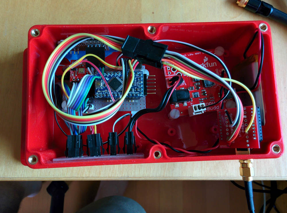
Rather than go through all the iterations, I’m just going to present the final product. It looks like this:
Here’s the weatherstation hardware, mounted in the watertight box. The Arduino Pro Mini, mounted on a little stripboard, is on the left, the solar battery charger on the right, and the XBee attached on the bottom right with the RP-SMA antenna connector coming out through the box.
Since the Arduino Pro Mini is a tiny board, I used a piece of stripboard that I had lying around to make connections. A JST connector connects the battery charger to the board, and the 3.3V regulator on the Arduino board also supplies the XBee and the sensors with 3.3V power
There are 3 connections to the I2C sensors, the pressure sensor (visible as a little red breakout board to the left of the Arduino in the picture), the light sensor (mounted at a little window cut in the top wall of the box), and the temperature/humidity sensors, which are mounted in an external housing and connected to the box with one of the black micro-fit connectors.
The two digital inputs, charge and fault, from the battery charger are connected with the “computer fan” connector along the lower end of the battery charger board. These are open-drain outputs, so the built-in Arduino pull-up resistors are used to convert them to high or low inputs.
The analog inputs require a bit more circuitry. Since the A/D converter measures voltages relative to a reference, we need a known voltage to compare to. Luckily the Arduino has a built-in 1.1V voltage reference that can be used for this purpose, but the hitch then is that all voltages must be converted to be no higher than 1.1V, since that’s the largest voltage that can be measured. The supply voltage measured through a voltage divider of 100k/470k ohm, which gives us a max measured voltage of 6.3V which is plenty since the Li-ion battery maxes out at about 4.3V.
The UV sensor, which is mounted along with the light sensor in the window of the box, also outputs a voltage that’s higher than 1.1V, so it’s also connected through a voltage divider, 100k/220k ohm.
The wind direction meter also is read with the ADC. Depending on the wind direction, there are 8 different switches that can be closed, each connected to a different resistor. By using this unknown resistor as one part of a voltage divider, we can measure the voltage and calculate the resistance. However, the resistance of this divider is fairly low, it’s a fixed 10k resistor and a variable one that can be even lower. Hence, the divider would consume quite a bit of current if it was always powered. Instead of connecting it to the supply voltage, it’s connected to one of the Arduino digital outputs, so it can be turned on when making a measurement and kept low when not. That way, it’s only consuming power when needed.
Finally, the wind speed and rain meters are just switches, so they are connected between a digital input and ground, using the internal Arduino pullup resistor. Thus, when the contact closes, the input will go low, and this can be detected. I’ll have more to say about this in the software post, but the Arduino has interrupts that can detect when an input changes, and even at what time, so this makes it possible to keep monitoring these even when the Arduino is sleeping.
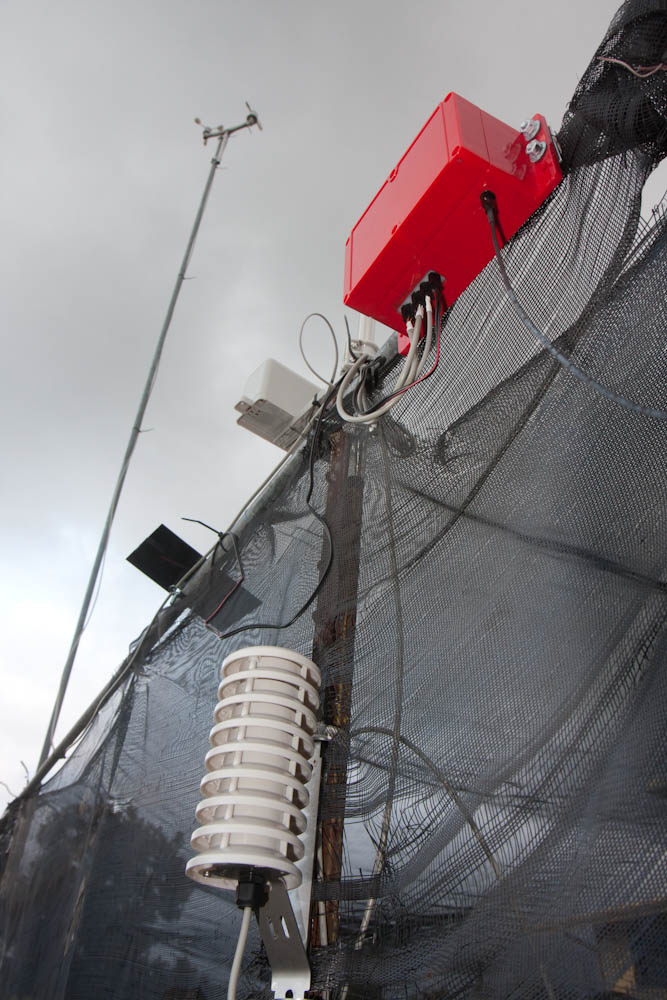
That’s pretty much it for the hardware. It’s all mounted in a weatherproof enclosure out in the yard, with the wind meters on a tall pole to get above the trees:
Here’s the weatherstation hardware. The temperature and humidity sensors are in the shielded enclosure at the bottom and the wind meters on top of the tall mast. The solar cell, rain bucket, enclosure, and the antenna are all mounted on the frame of our “greenhouse”.
I’ll write more about the software later, but it’s working. This is nice, because we’re getting hit by a hurricane later today, so it’ll be interesting to see the data (and see if anything blows away).
To wet your appetite, here’s the real-time measured wind and rain:
The link to all the plots is here. I’ll write more about the software once the hurricane has passed — assuming the house still stands!
Once things happen, they happen quickly! After getting the county permits, it took ProVision 3 days to get here to start work, and 1.5 days to finish the install.
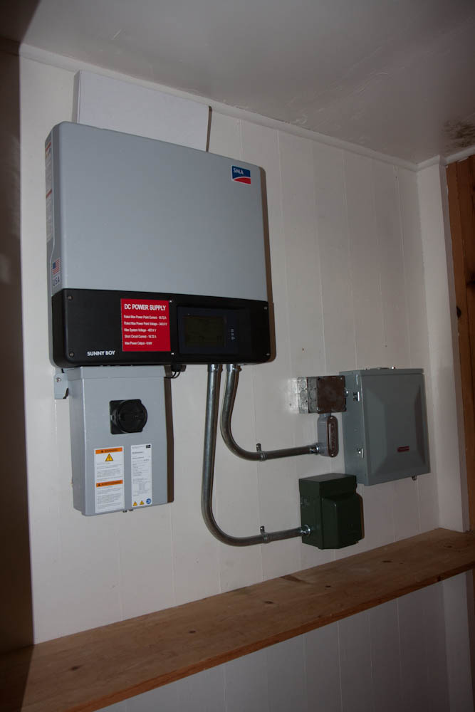
The first day they pulled the wires from the meter to the new subpanel in the garage in a long, snaking conduit going under the eaves and then across to the garage, where the inverter is mounted. The inverter is in a closet in the garage:
The SMA Sunny Boy inverter, hooked up to the new subpanel in the garage closet.
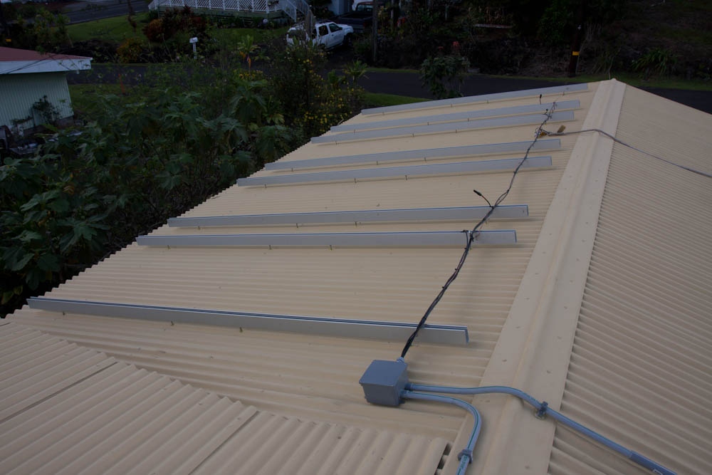
Then they mounted the conduit for the DC wires up to the panels, as well as the rails that hold the panels themselves:
The first day consisted of electrical wiring and installation of the mounting hardware for the PV panels.
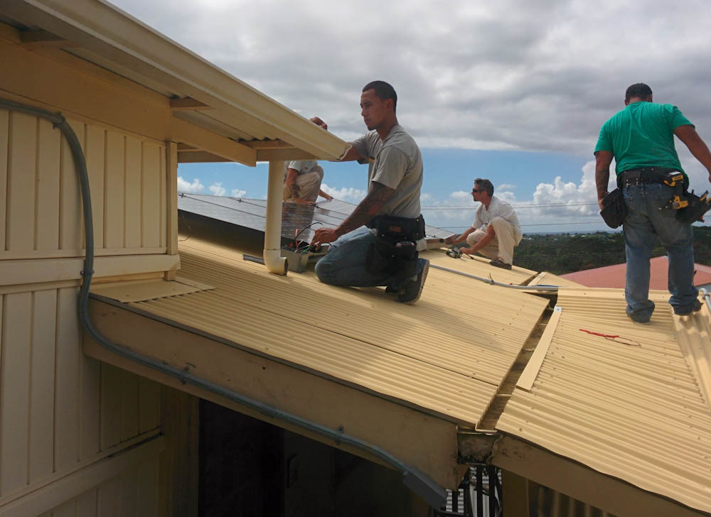
On the second day, they just installed the panels themselves, pulled some final DC wire, and hooked them up.
The ProVision guys in the process of mounting the final PV panel.
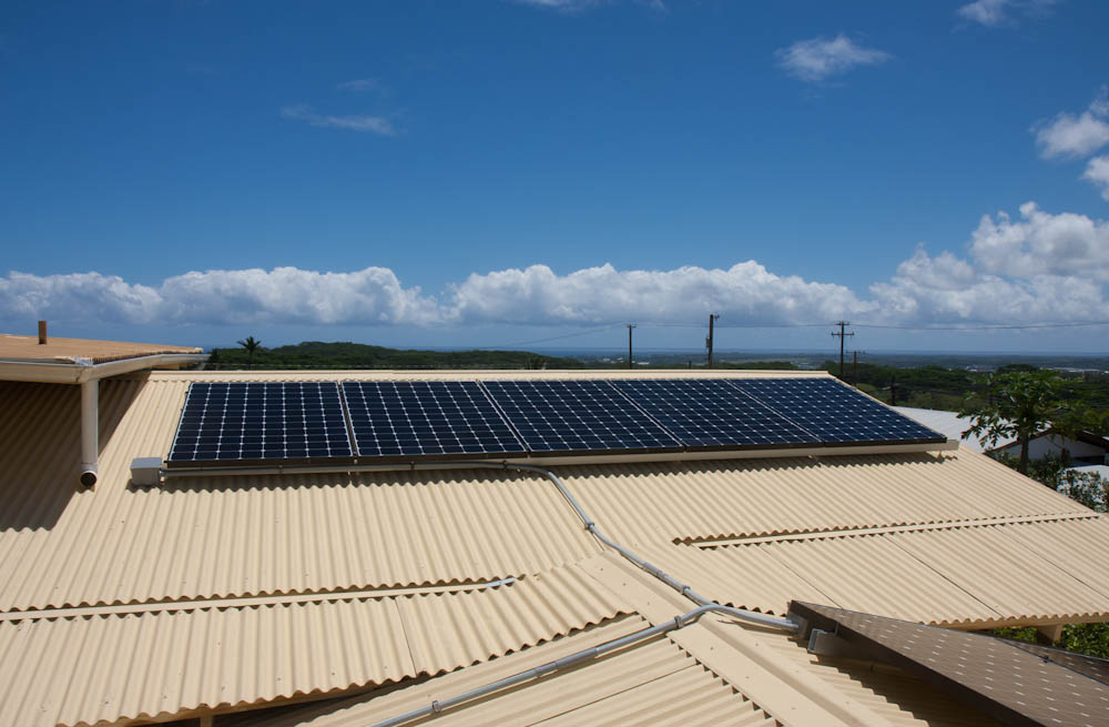
Now, the roof looks like this:
Here’s the roof now, fully equipped to supply our energy needs, without fossil fuel.
We can’t connect the panels to the grid until the utility has inspected them, but the inverter has a standalone functionality that gives you a backup power outlet if the power is out. We can use that, which seems like a good thing since tomorrow we’re being hit by Hurricane Iselle! I’ve determined that we actually can run the fridge on it, so this will come in handy if the shit hits the fan. Let’s hope it doesn’t come to that.