An exercise that almost everyone that starts working with fiberglass encounters right away is that of building a heated box for epoxy storage. The epoxy should be warm when used, somewhere around 30C or 90F, otherwise its viscosity is higher and it’s more difficult to wet out the fabric. If you don’t store it at that temperature, you’re faced with heating up the gallon-sized container of resin from its storage temperature before you can start working, so most people build a small heated box where the epoxy can live. (I think a second reason is that the hardener can crystallize if it sits at too low temperatures. You can recondition it by heating it up, but you may not notice that it’s started to gunk up your epoxy pump which will screw with your resin to hardener ratio.)
I decided to build a simple 2’x2’x1′ box out of plywood and insulate it with the same kind of styrofoam sheets I’ve been using to insulate the work shed. The inside would have two compartments divided by a shelf, a small one on the bottom where the heating element was and the main epoxy storage compartment on top. I just put the whole thing together pretty quickly without much thought to appearance, but I did decide to laminate the 6mm plywood shelf with fiberglass, not so much because I thought it wasn’t strong enough but because I didn’t want it to suck up the inevitable epoxy spills. It would also give me a chance to try laying up epoxy on wood.
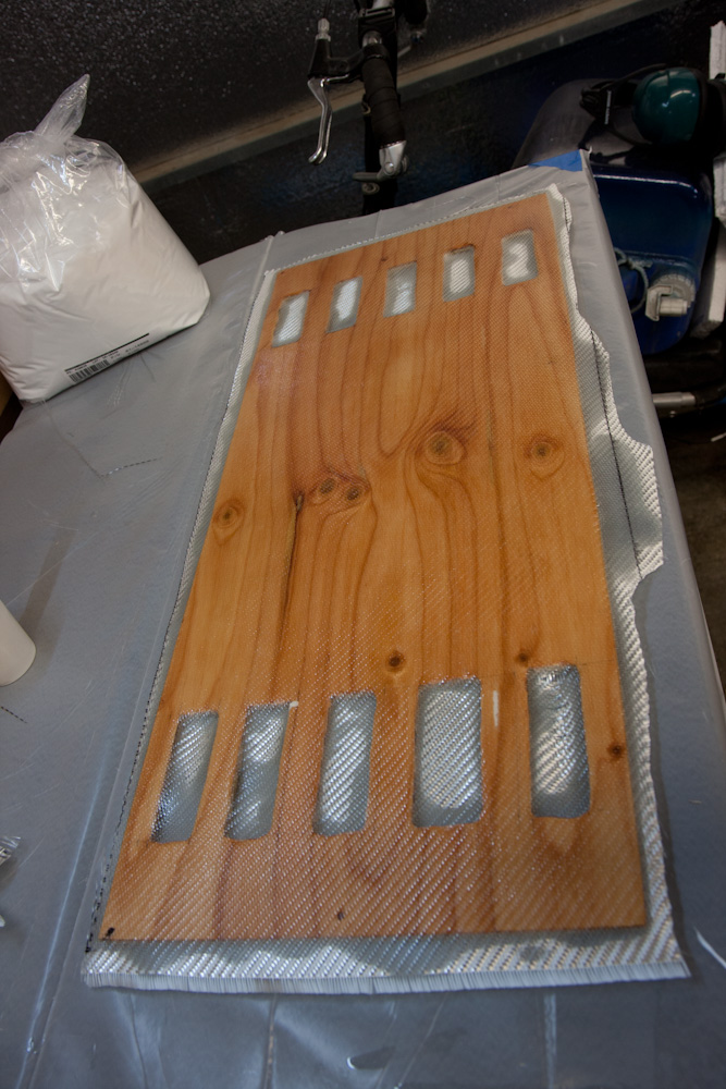
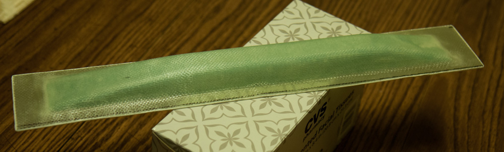
Laying up the hotbox shelf. The holes are so air can circulate through the two compartments.
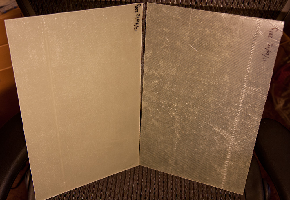
The most obvious thing from this exercise is that wood sucks up epoxy like crazy. I’d wet the wood, then put the single ply of BID on there, and then after a minute it would look totally dry. I’d add more resin, then the process would repeat. It would have been interesting to weigh it to see how much resin it ended up infused with.
I also added a ply of BID to the exterior bottom of the box and across the edges since the plywood was only attached in the corners. This gave the box some extra stability and me an opportunity to practice making corners, filling gaps with micro, and peel plying the edges to avoid sharp glass needles poking up out of the surface.
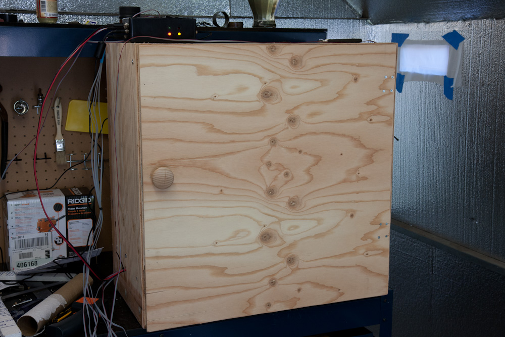
The exterior of the hotbox. I didn’t put much effort into making it pretty, obviously.
So far so good. Time to do the heater. It seems a lot of people just buy a thermostat and connect it to a light bulb inside the box. This would work, but seemed way too simple… Those of you who have looked at my old “projects page” on my home page may have seen the steam boiler monitoring system I built when we lived in Massachusetts. When we moved, I tore out the temperature probes and the box, and this seemed like a prime opportunity to reuse that stuff. It would also make it possible to add temperature control of the shed itself at some point.
The old system used a pair of “Series 1” XBee radios to send the temperature data to our server. These didn’t have enough juice to cover the distance between the shed and where we have the server currently, and then there’s the additional complication of the shed being made out of sheet metal, so an external antenna would be needed. Since none of my existing radios could use an external antenna and I didn’t even know if they would work, I got 2 new Xbee “Series 2” radios. These are quite cool in that they will generate a mesh network and route packets between them, so even if the destination is not reachable from the source node, the data will get there as long as there’s a chain of nodes that can talk to each other. Thus, if I had problems getting reception, I could add another node somewhere in between and it would act as a router.
It turned out they managed to talk to each other fine, even from within the shed as long as a door was open, so the external antenna I got must have quite a bit more gain than the little “chip” antenna the old one had. Still, it needs to work with the doors closed, so I mounted the antenna outside the shed.
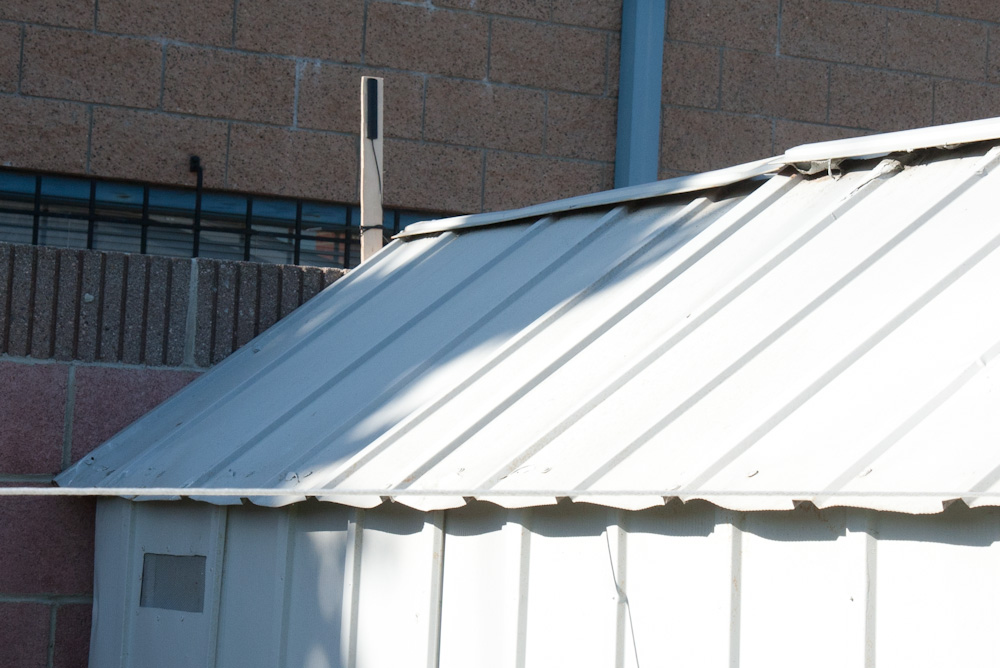
Since it was hopeless to get the XBee to work from within the sheet metal shed, I got a 2.4GHz antenna with a 10ft cable and mounted it on a piece of scrap plywood above the shed. One of the outside temperature probes also lives on that mast.
For controlling the temperature in the hotbox, I got two 2 Ohm, 25W power resistors at All Electronics (it’s nice to have found a good DIY electronics place in LA, even if it’s quite a drive). This is controlled through the Arduino PWM with a power MOSFET mounted in the Arduino box. With the resistors in series that makes 3A or 36W at full power. I mounted two of the old DS18B20 temperature probes from the boiler inside the box for temperature monitoring, one more on the power resistors themselves (to detect if the fan fails) and one to measure the ambient temperature outside the box. Two more temperature probes (the old living room ones with long wires) were pulled outside the shed to measure outside temperature, one where the radio antenna is and the other on the north side of the shed that never sees sun.
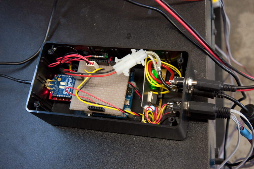
This is the enclosure that holds the Arduino, XBee radio, and the connectors for the hotbox heater and temperature probes.
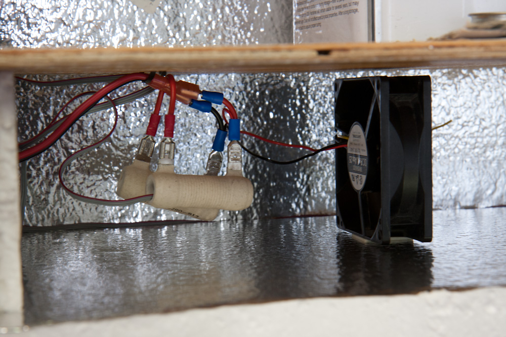
The heating elements for the hotbox are two 2 Ohm, 25W power resistors connected in series. An old computer fan is used to circulate the air over them.
The heating element is controlled with a PID controller on the Arduino, with an added open-loop control based on the temperature outside the hot box. Since the temperature inside lags temperature changes outside, the controller performance is enhanced substantially by the open-loop part. (This was used in the wine refrigerator, too.)
The software on the Arduino and on the server didn’t need many changes to work with this new system. I did have to do some coding to be able to upload new firmware to the Arduino over the radio link because the Series 2 XBees doesn’t quite work exactly like the old ones when it comes to controlling digital output pins on the remote end, which is needed to reboot the ATMega and start the boot loader. Basically, instead of just sending data straight over the serial line to the radio, you have to assemble them into packets depending on what you want it to do (send the data out over a remote radio’s serial line, change a setting, change a setting on a remote radio, etc). It’s more complicated but gives you greater control of what you can do.) Anyway, I worked on that over Christmas, aided by the book “Building Wireless Sensor Networks”, and that now seems to work reliably.
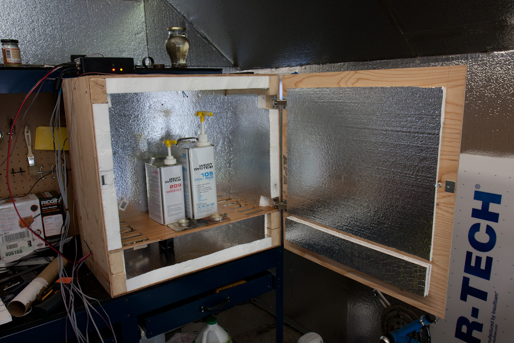
The inside of the hotbox. The walls are insulated with styrofoam insulation, the epoxy sits on the shelf, and the heating element is on the bottom. The Arduino controller box sits on top.
The system seems to work well. After putting it out in the shed and adding the epoxy containers, it maxed out the heater to heat them up, which took about 5h. By then it was getting colder and the power was going up until it maxed out when the temperature in the shed hit about 10C. (It got down to 4C outside the shed — I thought Southern California was supposed to be warm!) Then when the sun rose, the shed rapidly warmed up to 20C and the heater dropped down to 40%. It doesn’t quite have the power to keep the box at 30C, but as you can see above there’s no insulation around the hinges so there’s some room for improvement. Or it might be good enough, I doubt I’ll be doing much work when it’s 4C outside anyway.
The temperature data are shown on plots generated by our server. The plot below shows the temperature of the hotbox and the shed over the last 24h, updated in realtime:

Now maybe I can get around to making the second try of the test layup…