If you’ve read the the clutch posts #1 and #2, you know that I’ve been trying to get the clutch sorted for a while. The latest state of affairs was that the clutch was slipping uncontrollably and I’d then realized my clutch had NC35 pressure plates, which are 1.9mm thick instead of 1.5mm. So I ordered a completely new set of friction and pressure plates.
The parts showed up a while ago, but I got sidetracked by other little issues that I should post about. Finally, today I got back to it and took it apart again.
This is how the old stack looked:
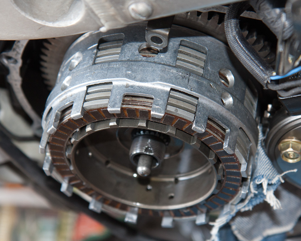
This is the old plate stack. Note how it doesn’t fill up the basket, and compare to the new one below.
Note that even though the pressure plates are too thick, it doesn’t quite fill up the basket. This is because there were only 9 friction plates instead of 10.
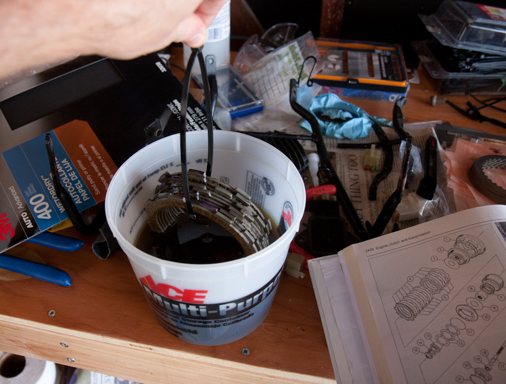
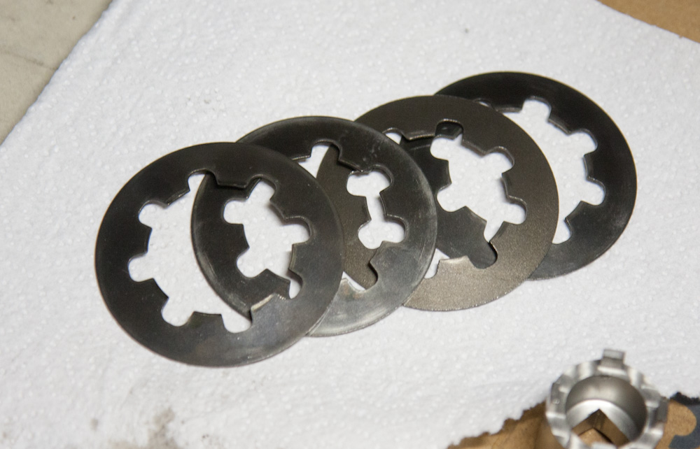
Soaking the clutch plates in oil before putting them in.
At this point I realized that there was something else missing. The NC30 has a slipper clutch, so when engine braking only the 3 inner plates do any work, the outer basket has a one-way clutch that just makes it spin. Between these two plates, there’s supposed to be a wide thrust washer. This was missing. Unfortunately I didn’t take it apart this much before, so I never noticed. These also seem hard to find, David Silver Spares, who seem to have most anything NC30 related, says there’s a 3-week lead time to find them. I decided that since it’s been running for God knows how long without it, I’d just put it back together and then take it apart again when I get a hold of one of those washers. It’s pretty quick to get the cover off. So I moved on.
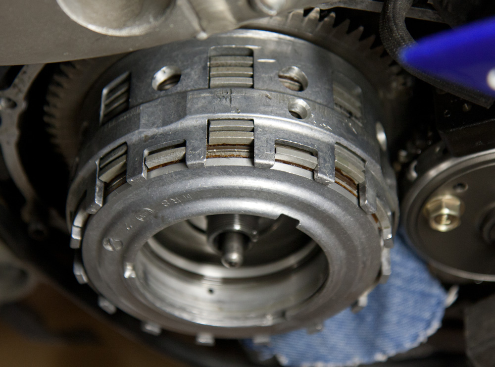
After soaking the new plates in oil, I put the new stack in. The 10 friction plates and 9 pressure plates pretty much filled up the clutch basket exactly, so this seems better:
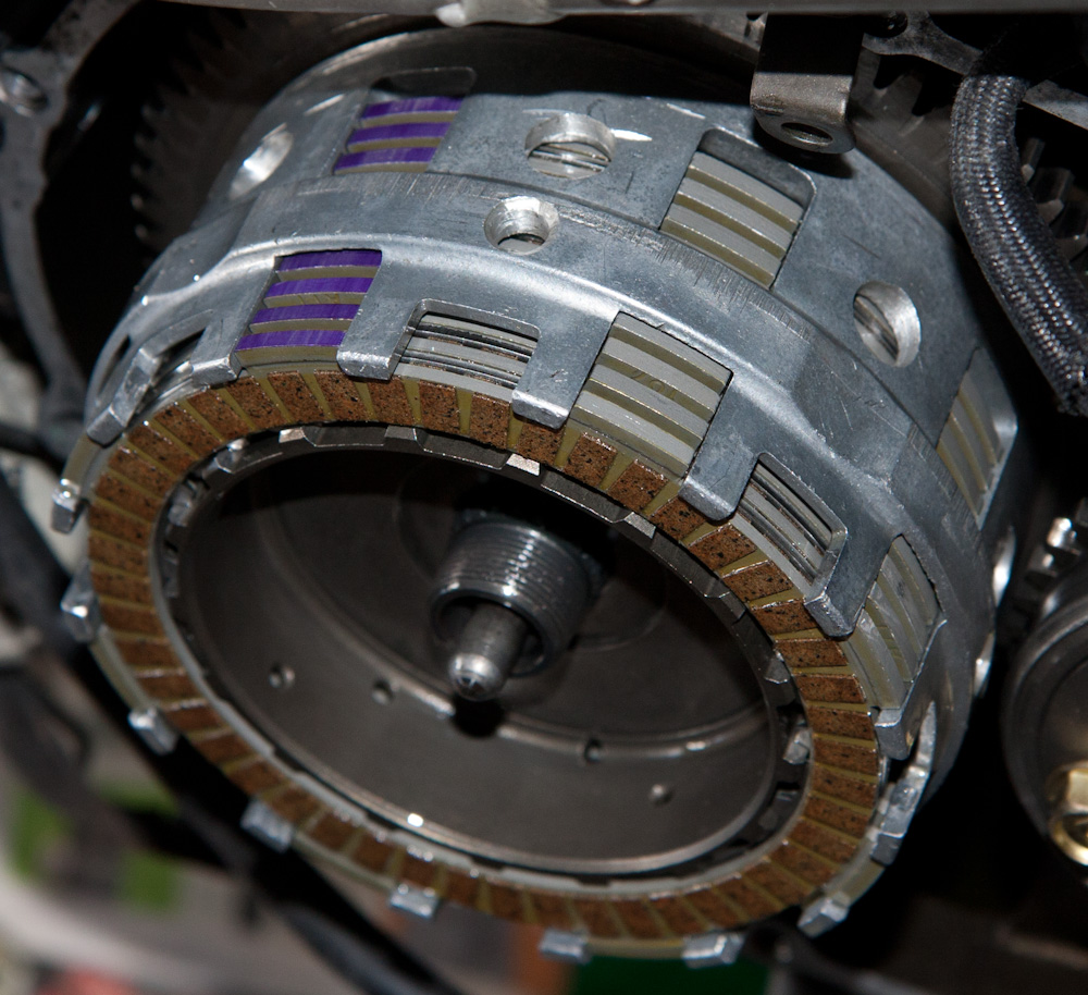
This is the new plate stack, which pretty much fills up the basket. The friction plates (with the blue tabs) are noticably closer together than in the old one — that’s the NC30 vs NC35 pressure plate thickness difference.
All the new plates had one of the tabs painted purple. The Haynes manual doesn’t say anything about this, but I assume it has something to do with alignment. There are no obvious marks on the clutch basket that might be an alignment mark, so I just put them all together.
I can just see how this unfolded now. For some reason in the past, they got NC35 pressure plates. When they put them in, all the plates didn’t fit, so they removed one set. That made the clutch slip, so they put in the 4th spring, ending up with the super-heavy clutch it had when I bought it. Now I’ve traced the same evolution backwards. If only they had done it right the first time…
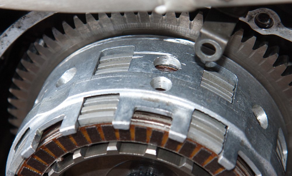
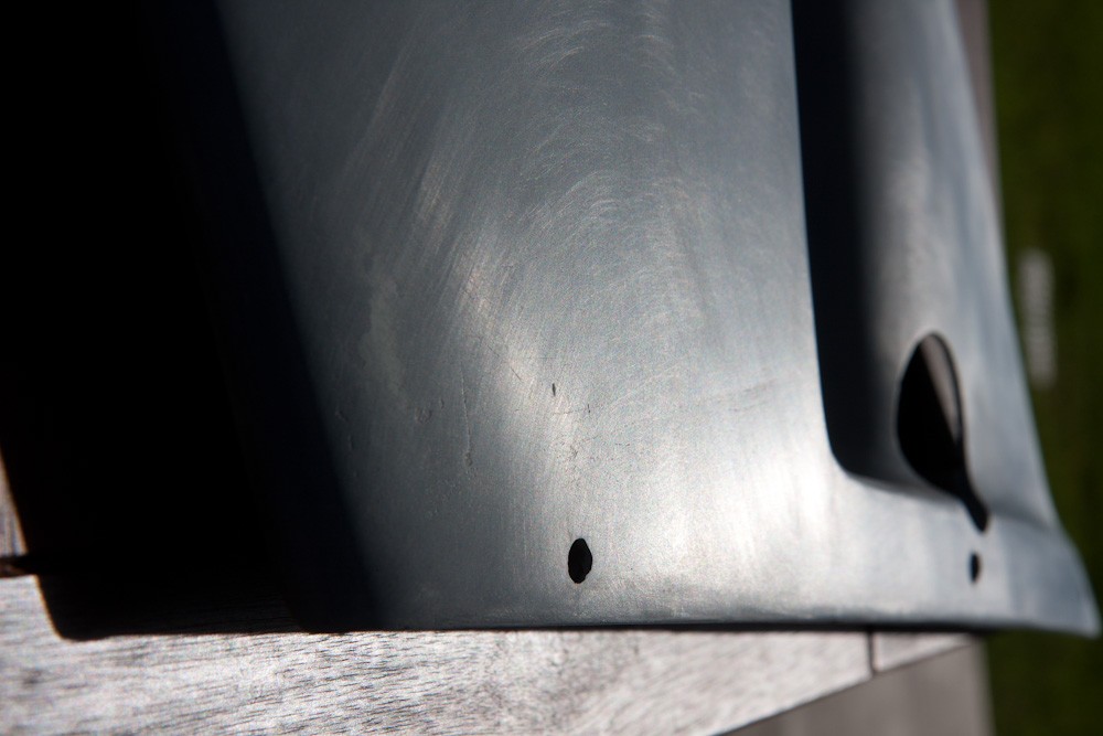
The outside of the clutch basket is scratched along the inner edge and also a few quite deep gouges in the top center of the picture.
When I was working in there, I noticed that the clutch basket has some strange scratches along the outside perimeter. They show up as very shiny in the picture above. There are surface scratches around the inner edge, and then a couple of quite deep gouges. As far as I can see, there’s nothing around that can touch the clutch basket at that point, so it’s like something came loose at some point.
Anyway, putting the whole thing back together, things started looking better right away. The clutch cable, which I before had to adjust all the way in on both ends to get a reasonable position, now is more in the middle of the range. I had blamed Tyga for making it the wrong length, but it seems I should have given them the benefit of the doubt…
Taking it out for a test ride, everything now seems to work fine. It didn’t slip, and it also doesn’t seem to drag when warm like it did before. So. I’ll call this a success! Once I get that thrust washer in there, I’ll hopefully close this chapter for a while.