As I described in the last post, the charge wiring on the NC30 was seriously fubar and needed a complete rewire. After a massive order of electrical gear, I had all I needed.
The first task was to find a replacement regulator/rectifier. I found a used FH008 MOSFET rectifier off of a CBR600 on ebay (actually I found two) and ordered it. According to the Rectifier/Regulator Upgrade post, the FH008 should be smaller than the FH0012/FH020 that they recommend. Those are really big and have a larger hole spacing than the stock R/R, making fitting it more of a chore.
Unfortunately it turns out that the FH008 is also really big and has a larger hole spacing:
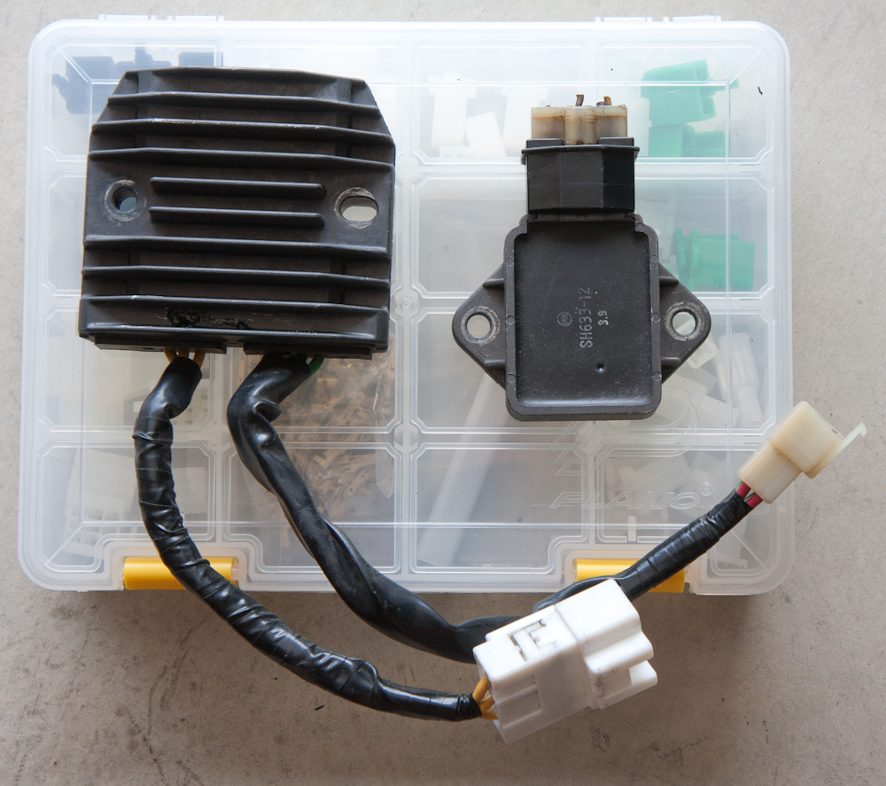
Here’s the new FH008 regulator on the left vs the stock NC30 one on the right. Quite a difference…
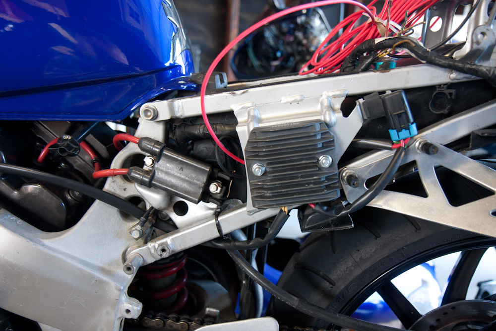
Because of its size, fitting it was a bit tricky. There’s not a lot of clearance to the fairing and the plate where the R/R is mounted is not flat. I cut the stock bolts off and drilled new holes. The regulator sits against the “ridges” on the plate, with spacers on the bolts. The stock one was mounted against the plate for cooling, but the CBR600 one actually sat on spacers, so I figured it would be OK to mount it on spacers here, too. After fiddling around finding the best position to clear the fairing, this was the result:
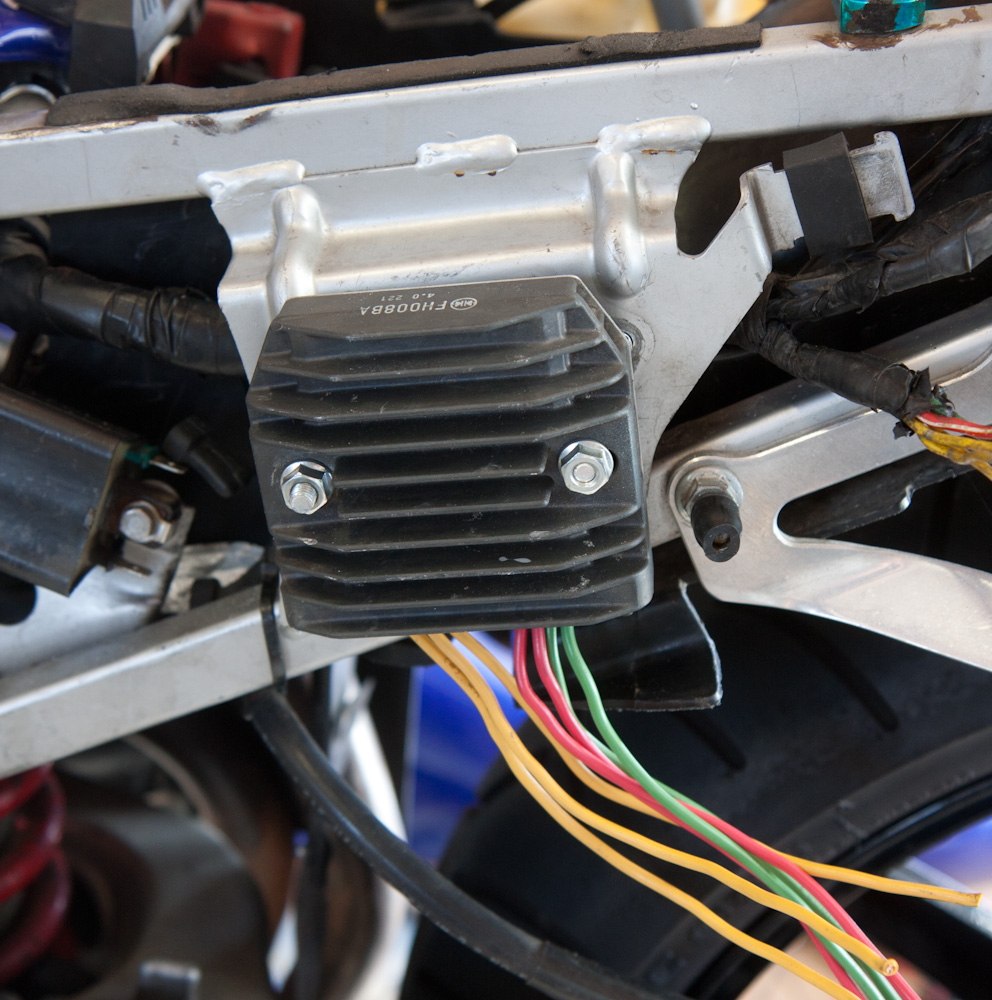
The new FH008 regulator/rectifier mounted where the old one sat.
The new regulator had connectors on wires, which I cut off. The regulator output has two pairs of wires which are just connected together. They are both 12ga (about 3mm^2), and one is more than enough for what the NC30 alternator can supply, so I just sealed one pair and mounted the Metri-Pack connector on the other. I also added a 30A fuse in another Metri-Pack connector. The stock regulator isn’t fused, but it seemed prudent to fuse it so if the output gets shorted to ground the fuse will blow rather than the alternator. The ground wire was attached to the same screw as the battery ground wire. (The stock ground connection goes into the main loom, which is grounded at the front engine mount, resulting in quite a long ground return path for the regulator. This way the regulator has a direct ground return to the battery.)
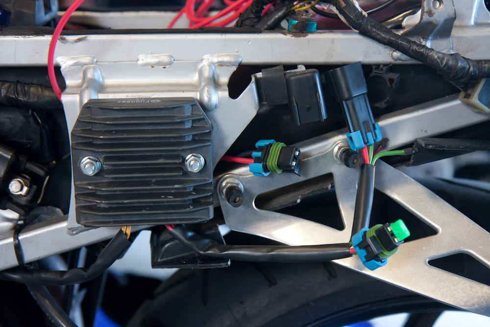
The new regulator wired up. The outputs are connected first to a Metri-Pack fuse holder to protect the alternator/rectifier, and then to a Metri-Pack connector.
The alternator wires were cut near where they come out of the alternator cover and another, 3-place Metri-Pack connector was added. These wires are quite thin (more on that below) so I wanted to get rid of as much of them as possible. Then I pulled three new 12ga wires that I spliced onto the yellow wires coming out of the regulator. The stock wires run in the loom to the right side of the engine and then over to the left side. Instead, I pulled the new wires in a plastic sleeve directly forward on the left side.
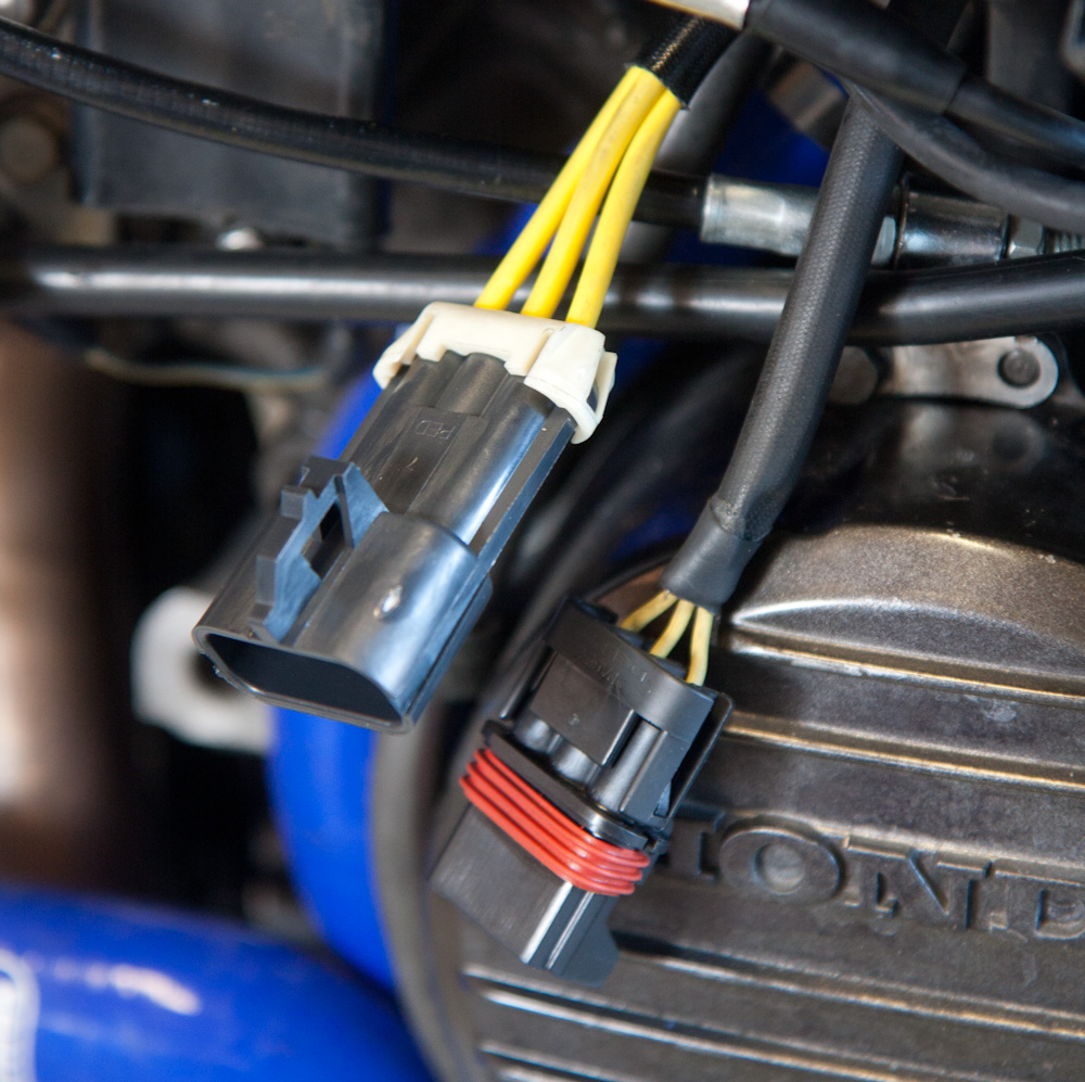
The Metri-pack connector for the alternator wires. Note how much thicker than the old ones the new wires are. The stock alternator wires are only about 16 gauge (1.3mm^2) and get quite hot.
The battery side isn’t wired yet, but I temporarily hooked up the output from the new regulator to the battery so I could check that the new regulator worked. It seems fine. Before, the voltage would swing violently depending on rpm. Now, I had 14.5V at idle and 14.7V at a few thousand rpm, much more stable. During the few minutes that I ran it, the new regulator didn’t even get noticeably warm. Neither did any of the new wires. The short length of old alternator wires are a different story though — they got hot, to the point that it was uncomfortable holding them.
The old 16ga alternator wiring is clearly undersized for the current the alternator supplies. I don’t know how much current the alternator can supply but to run everything on the bike and charge the battery it must be at least something like 20A. The current in the 3-phase alternator wires should then be about 13A. The table for wire sizing that I looked at said that a 16ga wire at 18A gets to 90C. That’s much too hot for me. I don’t understand why Honda couldn’t up the size of these, we’re talking a total of maybe 3m of wire. Hopefully it doesn’t get too hot for the connector!
The new alternator wiring in place. The red supply wire is not hooked up, but everything else is complete. The Metri-Pack fuse holder fits handily in the rubber grommet where the turn signal relay used to be. The lug for the ground wires is just above the lower subframe attachment bolt.
Next step is the battery side of things, to bypass the burned out master fuse connector and the long current path forward to the ignition key and then back to the fuse box.
Pingback: NC30 alternator rewire #2 | Patrik's projects