The NC30 rewire has been completed. The first post described the alternator/rectifier wiring, what remained was the battery wiring.
Since the master fuse and connectors to the alternator and the loads are integral to the starter solenoid and doesn’t lend itself to upgrading, I’d decided to bypass it completely. The new battery wiring goes from a ring terminal on the battery side of the starter solenoid through a beefy Metri-Pack 630 fuse holder as the new master fuse (those connectors are good for 46A) and then meets up with the alternator supply under the seat.
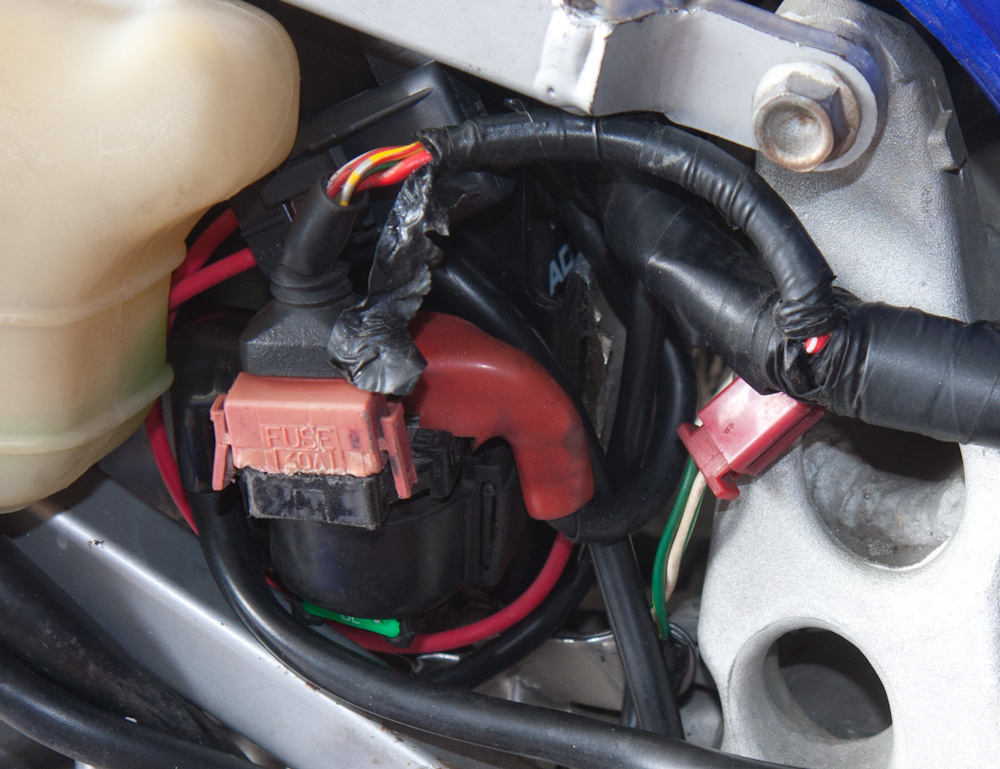
The new battery wiring. The MP630 fuse holder that replaces the master fuse can be seen behind the wires going to the starter solenoid.
In the stock wiring, the full current for the bike goes from the master fuse forward to the ignition switch and then back to the fuse box under the seat. On its way, it twice crosses a 3-circuit connector, the same type as the alternator wiring, on the right side of the engine. While this connector was in better shape than the alternator connector, it was clearly corroded and loose. It also seems to be that asking the ignition switch to switch that much current will be detrimental to its survival, and getting a new one won’t be easy.
For these reasons, I decided to use a 40A relay under the seat for switching the full load. As luck would have it, the ignition switch is a 3-pole switch and has two wires going back to the fusebox (presumably to spread the load a bit). But this means that you have access to a switched circuit back at the fusebox that can be used to switch the master relay.
So, the 6 connectors going to the fusebox were cut. The two supply wires (that used to connect to the ignition switch, were instead connected to the switch output of the relay. The two wires going to the ignition switch were connected to the supply and to the relay input, and then the other side of the relay input goes to the repurposed ground wire for the alternator. It all looks like this:
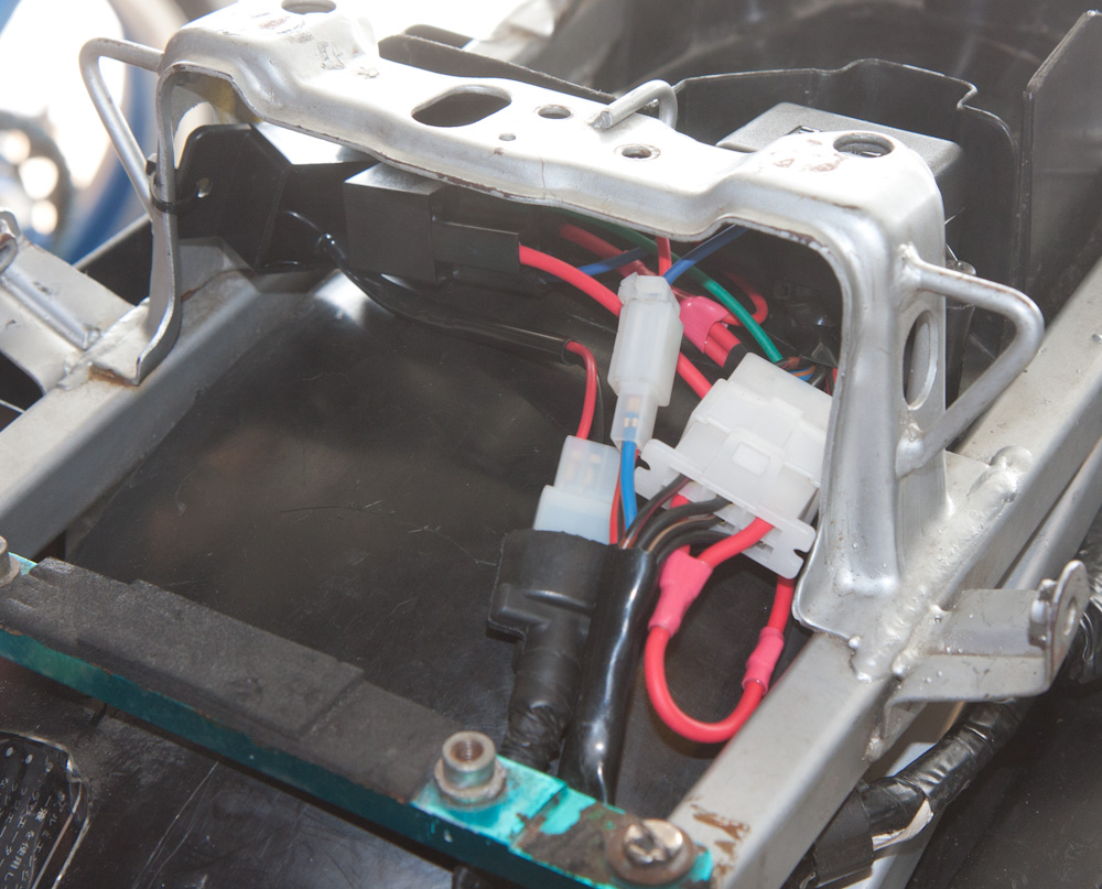
The master relay that takes the place of the ignition switch is under the seat, in the top of the picture. It connects to the fusebox with a six-way connector. The ignition switch controls the relay and is connected through the smaller 2-pole connector. (The other 2-wire connector, with the rubber cover, is the connector for the new solid-state blinker relay mounted to the left of the master relay.)
On the right side of the engine, I cut off the old connector to the ignition switch and crimped a new, smaller, 2-circuit connector on it instead. I still want to replace one more corroded connector by the engine, the one to the right handlebar. Luckily I have a replacement, so that shouldn’t be a problem. I probably should also secure the big connector to the alternator so the stator wires don’t wear off. Since they are much thinner than my new wire, all the bending happens where they come out of the connector.
All in all, it seems to work beautifully. The voltage is stable around 14.5V. Hopefully that will be the end of electrical problems. No, wait. I still have to add the second H4 connector for the headlight…