Things are slowly proceeding on the engine front as I’m meticulously going through some things while waiting for parts for others.
I got the cam gear thrust bearing endplay, mentioned in the last post, set right only to realize that this added to the free play in the gears (they are helical, so end play translates to angular play; or maybe it was just easier to notice once the cam turned more freely) to the point that it was outside of the spec. I’m banking on this being because the aluminum cam gear is worn, so I ordered a new one from CB Performance. The cam gears are supposed to be available in different sizes to account for tolerances in the spacing between the crank and cam shafts, but it appears most aftermarket parts only make the “0” standard size. If a new gear doesn’t get the play within spec, I guess I have to go searching harder.
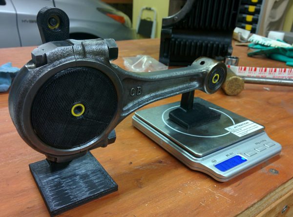
Next topic on my rather long list was to balance the connecting rods. This is a bit tricky, because you can’t just ensure they have the same mass. Because the big end of the rods is rotating with the crankshaft while the small end reciprocates with the piston, they also have to have the same center of mass (and, I guess, also moment of inertia, if you want to go all out). This is accomplished by weighing the small and big ends separately, which requires a jig to hold the two ends such that you can put one on the scale and it can rotate around the other.
After looking at some of these setups I realized I had some small ball bearings left over when I replaced the bearing in the anemometer on the weather station that could be put to use. I designed a simple setup in Fusion 360 and 3D-printed it in polycarbonate.

This is the 3d-printed connecting rod scale. There are two round bushings, made to fit the small and big ends, with two ball bearings each. The non-weighed end hangs on an extra link to minimize sideloads imparted on the scale.
I initially had tried to weigh the small end by mounting the rod on the crank bearing and letting it rotate around there. This did not work, the oil in the bearings apparently has enough viscosity to affect the weight enough to make the measurement useless. A reasonable standard to set is to make sure the rods are balanced to within 0.1g, and the measurement error was several grams.
The new setup worked much better. There is still enough variance that you have to make a bunch of repeated measurements. I think this is because the scale is sensitive to side load and there’s enough flexure in the plastic setup to make it a bit non-repeatable. The scale, with a resolution of 0.01g, also turns out to not be repeatable to better than about 0.1g when you start repeating measurements, even without the side load issue.
The maximum difference between the rods was about 2g (out of ~540g). That’s not bad, but we can do better. With some careful grinding on (hopefully) non-critical parts of the rods, and many measurements later, both the small end and overall weight spreads were reduced to +-0.15g at which point I called it a day.
However, it turns out that was for nothing. I did measure the big end bearing clearance on one of the rods using Plastigage (I haven’t used my set in years and it turns out it was all broken and missing, but I got one last measurement out of it) but I had not looked at the small end. The “How to rebuild your air-cooled VW” book says that the wrist pin should be a light push-fit in the small end bushing, without any perceptible play. Turns out my rods failed that test. Given how much play the old crank bearings had, it seems reasonable that the rods saw more side loads and coned out the small end bushings.
In the “good old days”, this would be fixed by pressing in new bushings and reaming them to size for the wrist pins. This is one of these things that are no longer economical to do when a new set of rods cost $150, you don’t get much shop time for that. So I ordered a new set of SCAT rods that are supposedly already balanced to within 1g. We’ll see, but hopefully I won’t have to do a lot of grinding there.
The other things that was supposed to get balanced was the pistons. The spread there was about the same, a couple of grams. However, in this case I started out measuring the ring groove clearances and discovered that at least a couple had bent or damaged ring lands, so we’ll be getting a new set of those too.
The old pistons were “AA” brand, so I ordered a new set of those. Turns out they make both a forged and a cast model, but the good people at aircooled.net claim the cast pistons are fine for engines that stay under 6500 RPM, which we do by a large margin. Since the forged pistons are about 3 times as expensive as the cast ones, I think cast will be fine.
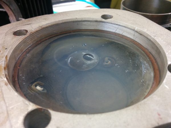
Moving on to the next item on the list: checking the combustion chamber volumes. If the combustion chambers aren’t the same volume, the different cylinders will run at different compression ratios and generate different power, contributing to uneven and inefficient running. Measuring the chamber volume is easy in principle. Cap the chamber with a piece of transparent plastic and fill it with water until it’s full. In practice it’s a bit more tricky.

Measuring the volume of the combustion chamber requires a bore-sized piece of plastic and a way of measuring volume. This chamber is almost filled with soapy water
Normally when doing this on a VW, you plop the plastic directly on top of the head. This allows you to just measure the volume of the chamber without the squish areas where the full bore is exposed. This volume is easily added later when you measure the deck heights, ie the minimum distance between the piston and the top of the cylinder. On the Aerovee heads, however, the second spark plug protrudes into the squish area, so it’s not possible to put the plastic directly against the top of the head. I had to use the 1.5mm copper gasket ring as a spacer. This is fine, I just have to take that into account when setting the compression ratio later.
There were two things making this procedure trickier than I hoped. First, I discovered that using soapy water worked much better than clean water, because the surface tension of the water otherwise prevented it from wetting the spark plugs and other small cavities. Second, It’s quite tricky to get all the bubbles out. In particular, air tends to get trapped in the narrow squish area and it’s hard to get it to come out to the hole in the middle. You also can’t tilt the head indiscriminately since then water will seep out around the perimeter. To get as good of a seal as possible, I coated the edge of the plastic with grease and set one of the cylinders on top of it to ensure it was pressed against the gasket.
I also don’t have a good way of measuring volume with high accuracy. Instead, I used the same precision scale and weighed how much water I had to take out of a cup and squirt into the head. This is a bit more error-prone since you have to ensure you don’t lose any of the water anywhere else. In practice, I repeated the measurements three times and got a spread of about 0.2cc, well within the accuracy needed. The chambers are about 68cc and with a swept volume of 545cc per cylinder, being off by 1cc results in a difference in compression ratio by about 0.12. It should not be a big problem to reduce the existing spread of about 2cc to less than 0.5cc.
Once the volumes have been measured, you of course have to do something about it. The obvious solution is to grind away material from the chambers with smaller volumes until they are equal to the largest one. But where do you grind? It appears with these heads, the differences are mostly from how deep the seat for the extra spark plug was cut, so it seems reasonable to take out material around that area. This should have a minimal effect on the airflow through the chamber, since you don’t want to end up making that uneven between the different cylinders either.
I’m currently in the process of modifying the chambers, so I’ll report back when this is complete.
Pingback: Engine guts 8: Balancing act complete – Patrik's projects