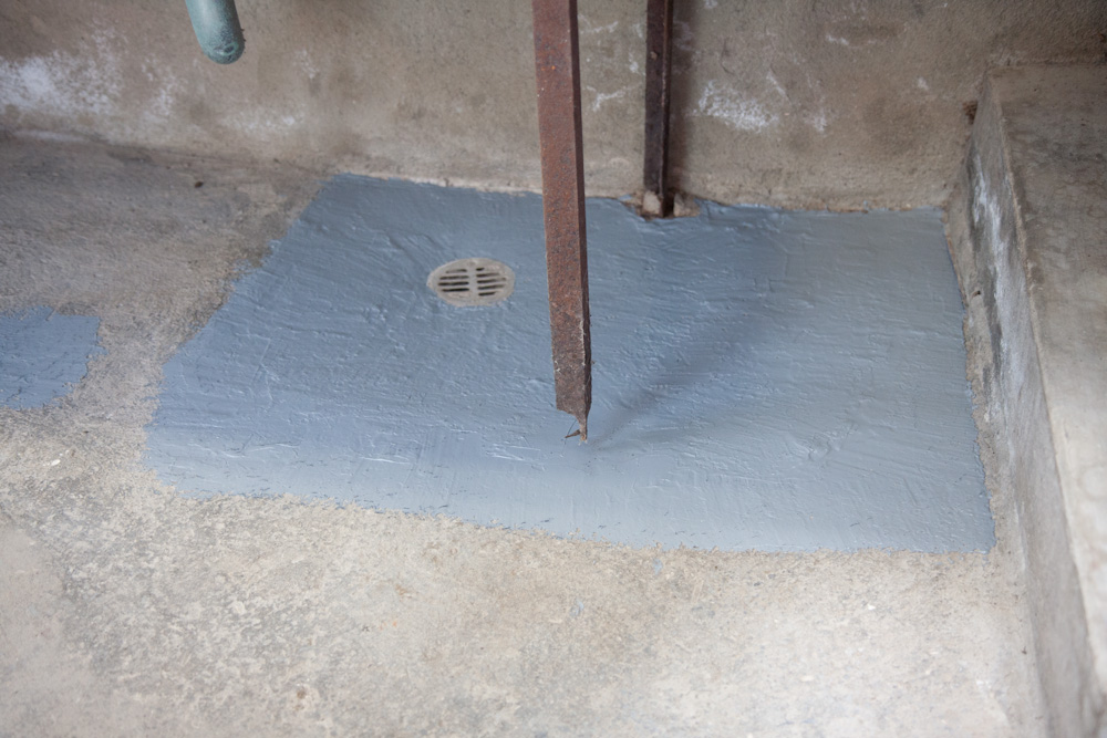
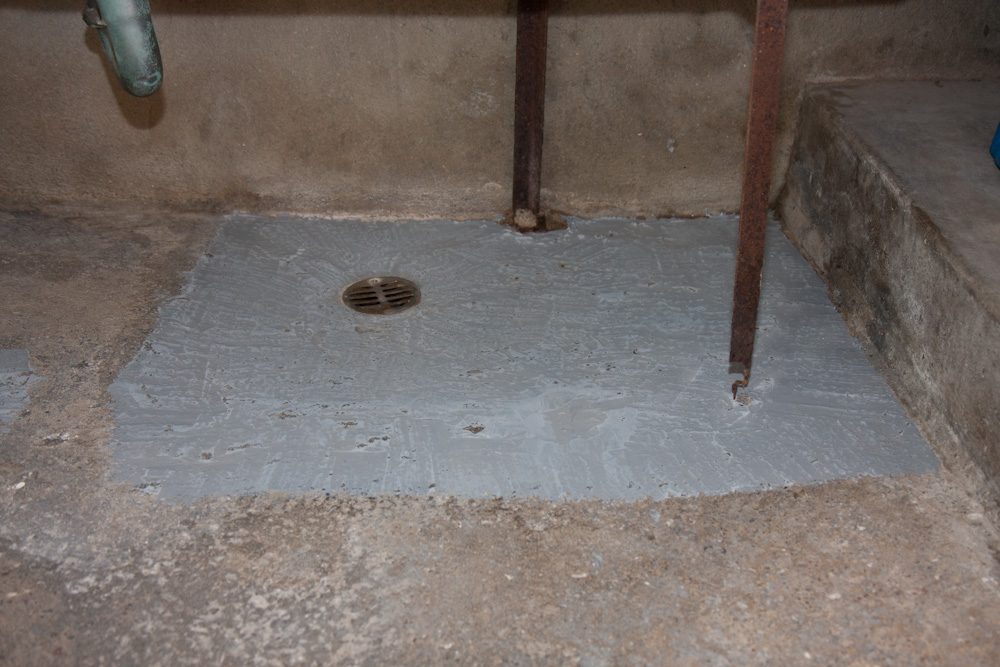
The basement was advertised as “partially finished”. We weren’t sure what to think of that, it has the scary shower, affectionately know by us as the “torture room” since it would make a great addition to some serial killer drama. The three rooms were also “finished” in the sense that they had carpet floors, while the rest of the basement has concrete, and some kind of inner wall made of thin white paneling.
Obviously, we weren’t too fond of the carpets, but we became even less fond of them at some point last December when we got 12″ of rain in 24h (for reference, that’s about the average annual rainfall in LA…) and discovered that the basement was taking in water! Not much water, but you don’t need a lot to soak a carpet. After a mad dash to quickly move all our boxes out of the room and mop up most of the water, we’d had it with the carpet. (It was obvious from the moisture marks on the paneling that this wasn’t the first time, either. What on Earth were they thinking!)
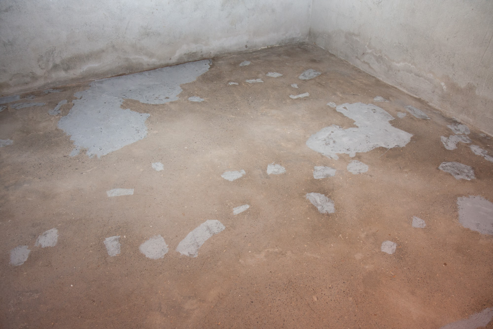
The good news was the carpet came up pretty easily (probably because the glue and foam had disintegrated from moisture.) However, because the carpet went under the paneling, we had to rip out the paneling too. No great loss. And finally the studs they had put up to mount the paneling. We were now left with an “un-finished” room:
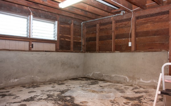
This is what the basement room looked like after ripping up the carpet and taking down the inner wall and studs.
Of course, now we were left with concrete covered with remnants of foam and old carpet glue. Since they had dutifully glued down the carpet over the nice wooden steps leading into the room, I brought out the remains of my favorite methylene chloride paint stripper to get it off.
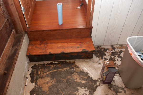
To get the carpet glue off the steps down into the room, we brought my favorite methylene chloride stripper out of retirement.
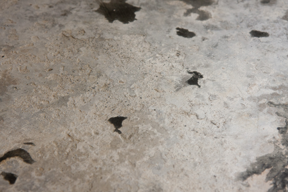
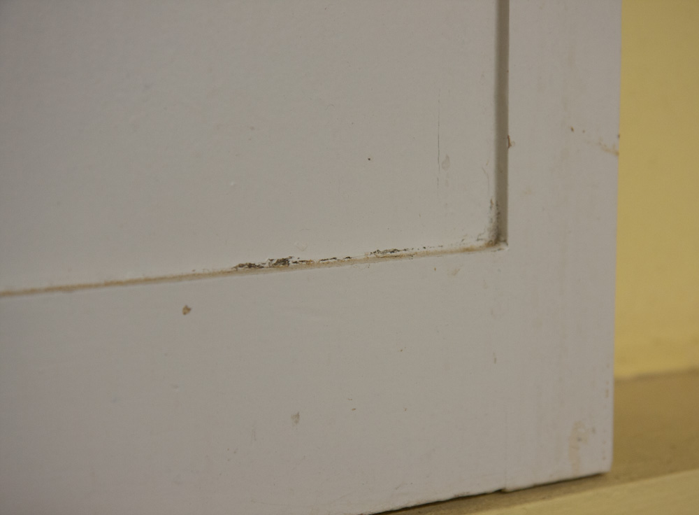
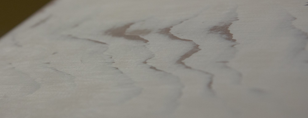
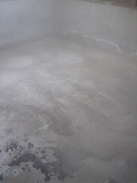
The concrete also had these areas where it was turning into flaky dust, like this:
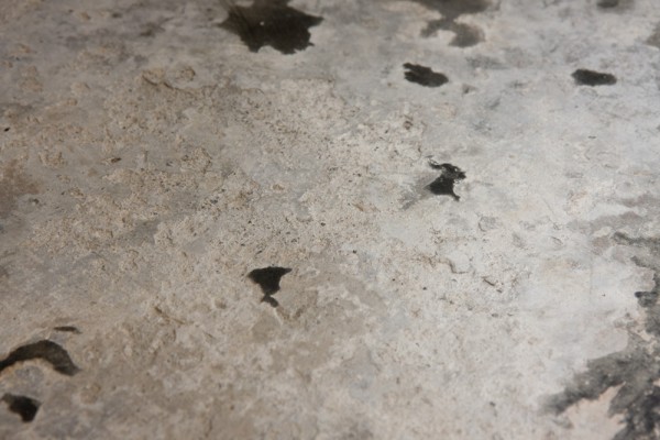
Some parts of the concrete was flaking up like this. The guy at the tool rental said this wasn’t concrete but something they used to level the floor a long time ago.
Clearly if we were to have any chance of coating the concrete with something, this needed to be cleaned up. The guy at Puna Rentals that I talked to about getting some machine to grind down the concrete with said this probably wasn’t really concrete but rather something they used to use to level the floor in the old days. It should come off without much problem.
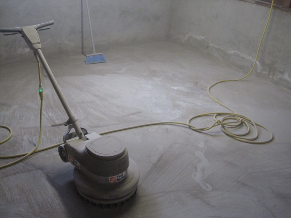
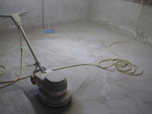
Puna Rentals only had a gas-powered concrete grinder, which was not an optimal solution to run in a basement room, but Home Depot had diamond “concrete coating remover” blades for a floor buffer that could be used to clean off concrete. The blade was $60 per day, in addition to the machine, so there’s gotta be a fair amount of diamond in there…
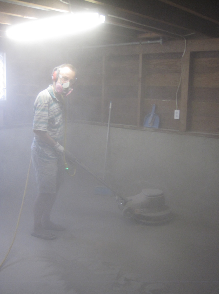
The machine was pretty effective, but it made a lot of dust!

Here I am grinding away at the concrete. The concrete turned into this extremely fine dust that basically got optically thick so I could no longer see what I was doing.
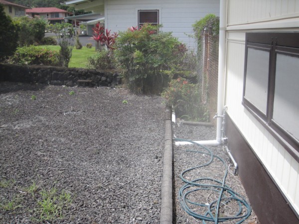
In the beginning I had the doors closed to the room to prevent getting dust into the rest of the basement, and I could only use the machine for a few minutes before the dust was so thick I could literally not see what the machine was doing! After a while, the trade winds picked up and I opened the doors to get some airflow. This blew most of the dust out the window and kept visibility reasonable. There was enough dust blowing out that it turned the lava rocks outside white.
The dust cloud coming out the window. The window is actually a bug screen, but it’s so full of dust that it’s essentially opaque.
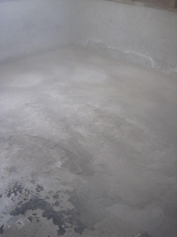
The “coating remover” blade was really quite effective. Here I’ve run it in the far corner, and as you can see, most traces of the carpet glue and stuff are totally gone.
It didn’t take long to get the remains of carpet glue and foam off, but the white flaky parts took some work. I also wanted to make sure the coating would have a fresh concrete surface to adhere to, so I kept grinding away. It removed a surprising amount, as evidenced by the fact that we ended up with upwards of 100lb of concrete dust in the trash can.
Most of the surface imperfections are now gone.
The end result looks like this. We now have a fairly even surface of healthy concrete, so there shouldn’t be a problem getting the coating to stick.
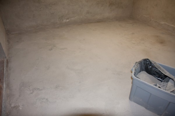
The final product, a pretty evenly ground down surface.
One possible issue might be moisture. I did a couple of moisture tests by putting a piece of plastic tarp down on the floor and seeing if we got any moisture, and I didn’t. However, the darker spot in the upper right sure seems like moisture. I’ll try again to make sure.
Since we had the machine for 24h, we decided to continue and work over the concrete in part of the rest of the basement. About half is in pretty good shape, with a non-slip coating on it, but the other half not so much. Unfortunately this meant that we had to clear out all stuff, and then we ended up with dust everywhere anyway. Just cleaning up all the dust practically took longer than grinding the floor did.
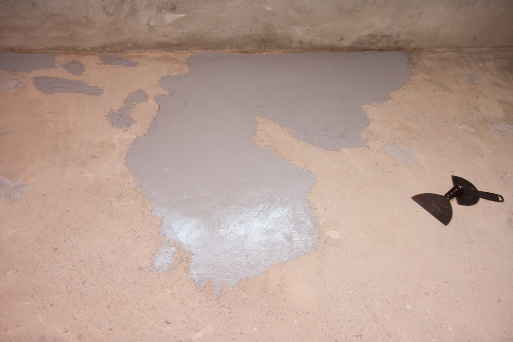
Next steps are to patch the holes in the concrete and get ready to apply the coating.