With the oxygen sensors mounted and the wideband controller box finished, I could finally start doing the wiring. While this seems like a simple task, I had a hard time deciding how to do it.
The big question in my mind was how to wire the power buss part of the fusebox. This requires connecting the incoming power to many fuses, so the wire somehow has to be split. The Metri-pack terminals in the fusebox will only admit one wire (and even if you managed to jam two in there, you’d ruin the sealing that makes the box waterproof) so some form of distribution circuit had to be created. The obvious solution is to crimp a bunch of wires together, but it’s kind of fiddly to create and it creates very thick and inflexible “bundles” of wires that are a pain to handle. However, any other solution would require some form of terminal block, which is exactly what I was hoping to avoid with the nifty, waterproof fusebox.
In the end, I settled on crimping the wires together with the “open-barrel” splices I got from Cycle Terminal back when I replaced the burned-out alternator wiring. After a few failed attempts, I finally got a procedure that worked and spent some time making the necessary distribution wires.

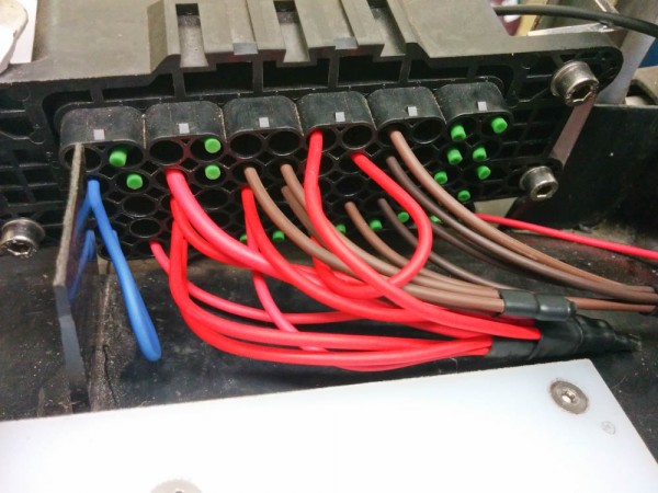
These are the main power distribution wires finally crimped together, heatshrinked, and plugged into the fusebox. The green “knobs” poking out of some of the holes are plugs that seal up unused holes.
It turned out OK, but there’s always the question of how well the adhesive in the heatshrink flows into the space between wires when you shrink many together. At least these are easy to pop out and replace if they should turn out to have a problem in the future.
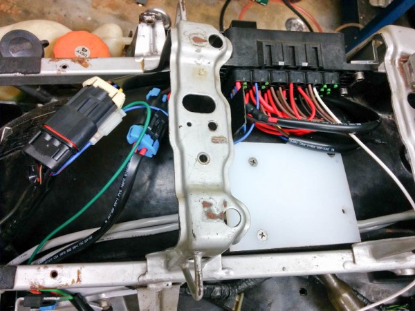
With the distribution wiring completed, next task was to get the battery and alternator wiring in. Back when I redid the alternator wiring, I added a fuse for the alternator in that wire. Since there will now be an alternator fuse in the fuse box, this was removed as was the stock fuse box and the main relay I added before. To be able to disconnect the main power, I added a 2-position Metri-Pack 280 connector for the incoming battery and alternator connections. The stock wiring for headlights, tail lights, indicators, etc, will be retained. They were connected to the fusebox via a 3-position Metri-Pack connector. At this point, the whole deal looks like this:

The stock fuse box has now been removed and those circuits connected to the appropriate fuses using the two Metri-Pack connectors on the left. The small 2-position connector connects the main relay to the ignition switch.
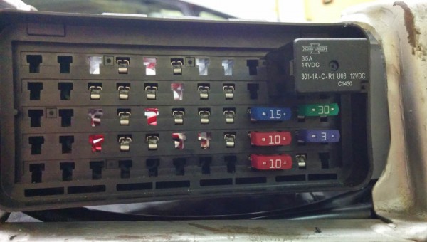
The Metri-Pack connectors are kind of large but they tuck up pretty well under the metal bar so there shouldn’t be any interference with the seat. The inside of the fusebox looks like this:

The main relay and the fuses for the alternator and the lights that were moved from the stock fuse box are now in place.
That was pretty good progress for a day’s work. There will be three more relays in the fusebox, one controlling the radiator fan, one controlled by the Microsquirt to enable power to the fuel/ignition system, and one that cuts said power when the kill switch is off. There will also be a bunch more fuses for the fuel/ignition components and the fan.
I haven’t touched any of the electronics wiring yet, but there are also a bunch of wires that need to connect the Microsquirt to the other electronics box and to some other sensors. Plenty more to do.
Pingback: Microsquirting the NC30, part #5: More wiring | Patrik's projects