High Performance Wine Storage System #3: The Lamp Panel

This is post #3 describing the wine storage unit upgrade. See the introduction post for the background.

In the ceiling of the cabinet interior was a “lamp”, meaning a single white LED, controllable with one of the front panel buttons. It didn’t really provide enough light to be useful, but it was already wired to the front panel. Since this was the one place where one could hide some components, I also decided that it would be a good place to put the humidity sensor and one of the temperature sensors. The two wires for the lamp could be reused for a slightly better illumination solution, but 4 more wires were necessary for the temperature and humidity sensors.

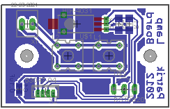
I designed a replacement circuit board (the original only had the LED, connector and a capacitor on it, but there’s enough room to put in everything else. For the illumination, I decided to use 2 of the leftover S-flux LEDs I used for the Passat headlight retrofit back in 2006. For humidity sensor I used a Honeywell HIH-4031 that I found on Sparkfun, and then the obligatory DS18B20 for temperature. Here’s the circuit board from Eagle:

Lamp board

The new lamp circuit board layout from Eagle.

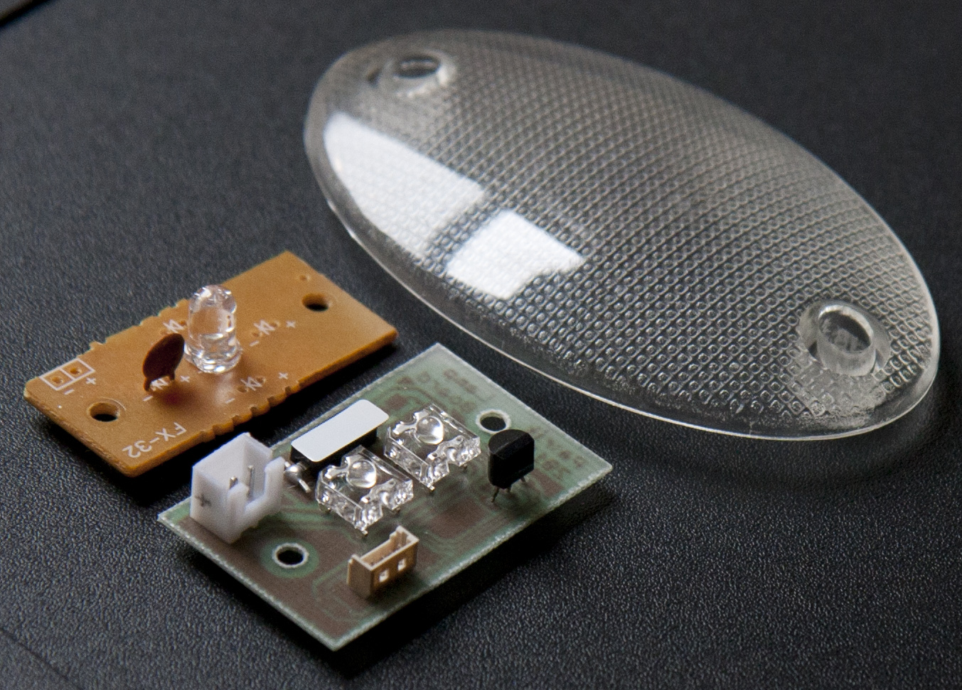
And here’s a photo of the old and the new boards along with the lamp cover. The white square is the humidity sensor with the protective film still attached. I guess I’ll have to drill a bunch of holes in the plastic cover so the humidity in the enclosure can equilibrate with the main cabinet.

Lamp board

The old and new circuit boards for the interior "lamp", with the plastic cover.

So far, I’ve only verified that the LEDs work, the rest will have to wait until the back board with the microcontroller is done. This is described in the next post.

High Performance Wine Storage System #2: The Front Panel

This is post #2 describing the wine storage unit upgrade. See the introduction post for the background.

The first thing that needed figuring out was how to redo the front panel. In the original setup, this is actually where the microcontroller is located, but that wouldn’t work for the redesign because there are only 3 wires connecting the front panel to the power supply on the back. It worked in the original, because the only signal that goes back to the power supply is the PWM output from the microcontroller, everything else is self-contained on the front panel. So there’s only power, ground, and one extra wire going to the front, and since these wires were run before the walls were filled with the insulating foam, it’s basically impossible to run more wires. Well, one wire… sounds like we’ll be using 1-wire!

What functionality needs to go in the front panel?

  • Output to the LED display.
  • Read the 3 buttons that are used to control the unit.
  • The internal “lamp” (a dinky little LED) is fed with a separate circuit going from the front panel to the lamp in the top of the interior, so that power needs to come from here, too.
Front panel

This is the original front panel. The two buttons to the left of the display control the temperature set point, the button to the right toggles the interior "lamp".

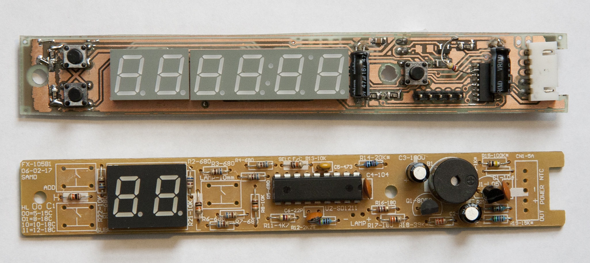
As you can see, the original only has a 2-digit display which displays the current temperature (or the set point when changed) in Fahrenheit. I thought it would be nice to have a bit more feedback since the functionality will be enhanced significantly. There’s room for a 6-digit display if one cuts out a larger window and moves one of the buttons, so that’s what I went for.

So, how do we control a 6-digit LED display, read 3 buttons, and switch a circuit on and off over one wire? I figured there had to exist some kind of 1-wire controllable switch, and after some searching I came across this application note by Dallas/Maxim: “One-Wire Network Controls Remote SPI Peripherals“. It describes how to control a MAX7221 SPI LED display driver using 3 1-wire switches. Ha, there’s the solution!

Instead of the DS2413 units (each of which has 2 switches) used in the article, I elected to use the DS2408, which is a 8-channel general purpose I/O switch. Each of the 8 channels can be an output, switchable using 1-wire commands, or an input, where you can both read the current state of the input as well as whether the input has changed state since the last time.

So the strategy was to use the one available wire, in addition to +5V and GND, going to the front panel to connect the DS2408. This would then simulate a SPI output as described in the article, talking to the MAX7221 display driver, which can drive the 6-digit LED display. The 3 front panel buttons would be connected to the inputs on the DS2408 so that their state could be read over the 1-wire interface. Finally, the LED lamp would be controlled by a MOSFET that could be turned on/off with another output on the switch. All in all, this would use 3 (for the SPI) + 3 (for the buttons) +1 (for the lamp) = 7 of the 8 channels on the DS2408. Sounds like a go.

There is only room for a roughly 150x20mm circuit board in the front panel, so fitting the display, buttons, 3 pretty large SMD ICs, and wiring up the signals to the display was a bit tricky, but it worked. (I bought a hobbyist license for Eagle CAD a while ago when I realized that I was going to be making circuit boards, so at least I had a good tool.) It was also not exactly cheap, the MAX7221 is ten bucks! (For comparison, the Atmega 328 microcontroller in the Arduinos is less than $5, and that’s a whole computer…) But whatever. Here’s the two sides of the board from Eagle:

Front panel board

The front and back sides of the front panel circuit board in Eagle.

And here’s the new board along with the old version. There are some empty spots on the old board since I pillaged the connectors and buttons. (Out of respect for the poor Chinese workers who soldered the board, I’m not showing the solder side of the original board…)

Front panel circuit boards

The new (top) and bottom (old) circuit boards for the front panel.

This was the first real board that I etched with the “PCB Fax-in-a-Box” toner transfer set. It worked pretty well, there were only a few places where it had to be patched. As suggested in the instructions to the toner transfer set, I through-plated the vias using a rear window defogger kit (basically seems to be emulsified copper in a carrier that dries). After soldering all the components on, I had a few problems that were related to me forgetting to wire the DS2408 reset pin to a pullup resistor, so it would reset itself randomly. Once that was fixed and the board was prototype-wired to an Arduino, I could reliably communicate with it. If the faster “overdrive” 1-wire timings are used, the throughput is high enough you can drive the display at maybe 20 characters per second even with the quite inefficient 1-wire -> SPI conversion. Plenty fast for what we need.

Next: software. I wrote libraries to control the DS2408 and MAX7221 and added overdrive timings to the OneWIre Arduino library. My newly purchased digital storage oscilloscope came in handy trying to debug the communication and getting the DS2408 protocol right. I haven’t finished implementing the UI since I don’t have the remaining functionality yet, but it’s started. It uses the “State pattern” to implement a state machine controlled by the buttons. It cycles through displaying temperature and humidity, temperature set point is changeable with the buttons, and there’s a programming mode that so far enables changing the display brightness and saving this to EEPROM so it’s persistent. What’s written works nicely, the rest will come once we have a functional unit. The code is in my Arduino repo on bitbucket.

So far, so good. What remains is designing the main controller board with the Atmega328 plus wiring up the cabinet with the sensors. The next post describes the remake of the little lamp inside the cabinet.

The High-performance Wine Storage System: introduction

Lately, I’ve been working on a wine storage unit. This is the first post in a series detailing what I’m doing.

When Chris Hayward left town for Heidelberg, he bequeathed his (non-functional) wine refrigerator to me. It didn’t work, but I figured it would probably be something simple that could be fixed. Kathy and I had talked about needing a solution for storing wine, since in the summer our apartment easily gets to +30C. The basement is better, but it instead gets down quite close to freezing in the middle of winter. It would be nice to have a temperature-controlled environment.

Wine Enthusiast

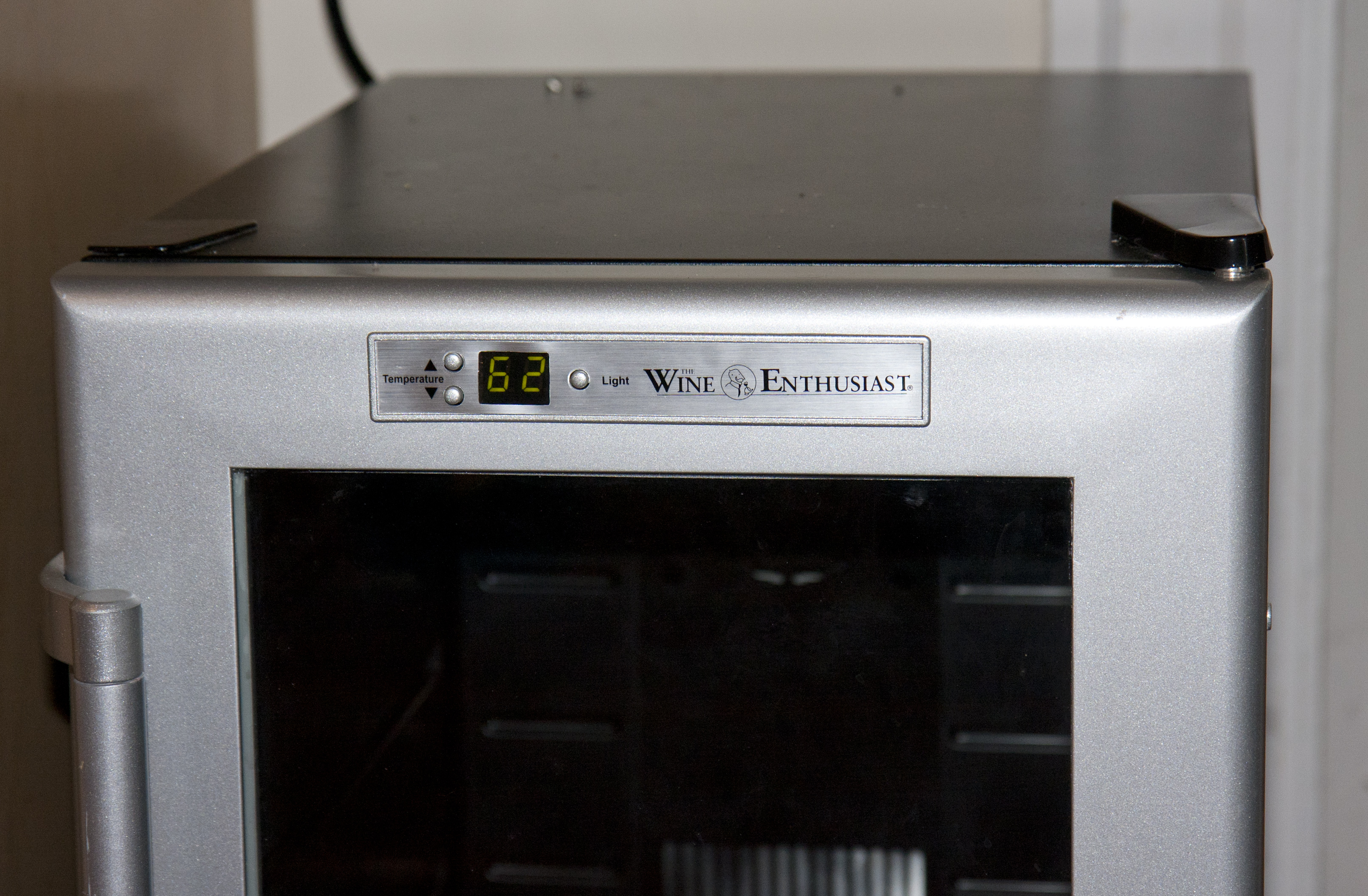
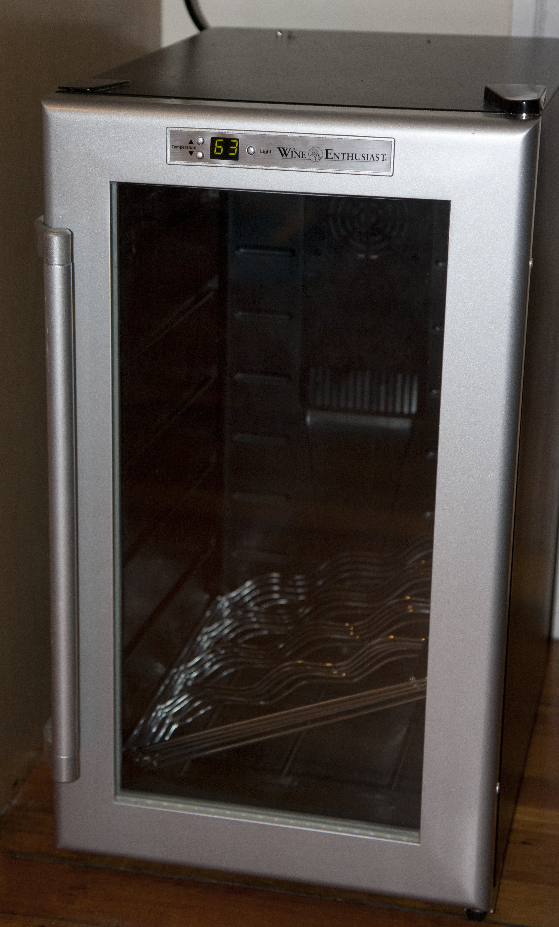
Project target: the "Wine Enthusiast 18 bottle silent wine refrigerator".

The wine refrigerator, made by “Wine Enthusiast”, shown above. The problem turned out to be a blown fuse, hidden under heat shrink tubing and soldered-in on the board. Clearly they want this to be user-replaceable… After replacing this, it started up fine. However, what a piece of junk…

The first thing I noticed as I was replacing the fuse was the extremely shoddy soldering job. The board looked like it had been soldered by an summer intern. The board also had clear signs of overheating around where the wires to the thermoelectric element attached (which is where the blown fuse is). Apart from those concerns, maybe I’m just nitpicking. However, it can’t even control the temperature.

Before going into this, let me explain how the thing works. (I’ll add some pictures soon.) It’s a thermoelectric cooler, so the core is a Peltier element. The hot side, on the outside, attaches to a large heat sink that is cooled by two 12cm computer fans. Inside the cabinet is a smaller radial fan that blows air across a smaller heat sink attached to the cold side and circulates it around the cabinet. Both fans and the thermoelectric element is attached to the same circuit, so there’s only one control loop. There are two temperature sensors. Embedded in the hot-side heatsink is a NTC thermistor which is connected to the power supply. I think this is just a safety to turn everything off if the fans should fail to avoid overheating the Peltier element. If this thermistor is unplugged, the output regulator is off. There is also a temperature sensor near the cold-side heatsink which is connected to the microcontroller that runs the unit. I’m pretty sure this is the one that feeds the control loop.

So what’s the problem? Say you turn the unit on. It’s obviously too warm, so the cooler turns on. The inside gets cooler, and eventually the control loop starts lowering the speed of the fans. What now happens is that, since the temperature sensor basically is sitting on the cold side heatsink, it gets even cooler due to the thermal inertia of the heat sink. Now the unit thinks the inside is too cold, and shuts off. The inside fan is not running, so the coldest part is obviously the cold sink. By the time it has heated up to the temperature set point, the general inside of the unit is now quite above the set point. So when the control loop turns on the fans just a bit, it starts blowing warm air across the temperature sensor. It now realizes the temperature is way too warm, so it turns full on, and the cycle repeats. Even though the controller really seems to be a PWM controller, because of this it essentially works like a bang-bang controller with something like a 10F hysteresis. So while it’s supposed to keep a constant temperature, it actually constantly cycles the temperature up and down by 10F. Brilliant. The point was to have a constant temperature for the wine, but instead we’re subjecting it to constant temperature cycles. (It’s true that the thermal inertia of the wine if the unit is fully loaded probably makes this less bad than it could be, but it definitely seems like a poor design.) To my perfectionist self, this clearly is an unacceptable solution. A redesign was in order.

What are the requirements on the upgraded “high-performance” wine storage system?

  • It should keep the inside temperature constant. +-0.5C should be easily attainable.
  • It should be able to use heating as well as cooling to accomplish this even if the outside temperature were to drop below the setpoint (as it would in our basement in the winter).
  • It should monitor the temperature as well as the humidity inside the cabinet.

Since the unit uses a thermoelectric element, heating is easily done by switching the current direction. Temperature monitoring should be done at several points inside the cabinet, not on the cold sink. To minimize the temperature variations inside the unit, the inside fan should always run at a low speed even if the Peltier element is essentially off. The 2-digit LED front display should be augmented to give better feedback.

As in my projects have tended to be lately, this is a nice application for an Arduino, some Dallas 1-wire DS18B20 temperature probes, and a few PID control loops. The next article will describe the front panel redesign.