Since the last post, which outlined the throttle linkage design, I’ve done some of the fabrication. Because the pieces are fully three-dimensional and not prismatic, it takes a bit of care to make sure that they can actually be fabricated. If you design some thing that has no parallel edges, it’s very difficult to hold it when milling subsequent operations, so I had to do some little “design for manufacturability” tweaks.
The first ones to be made were the cylinder 2 & 4 links. That went pretty smoothly, although the tolerances when the pieces were moved around weren’t great. Won’t affect the result though.
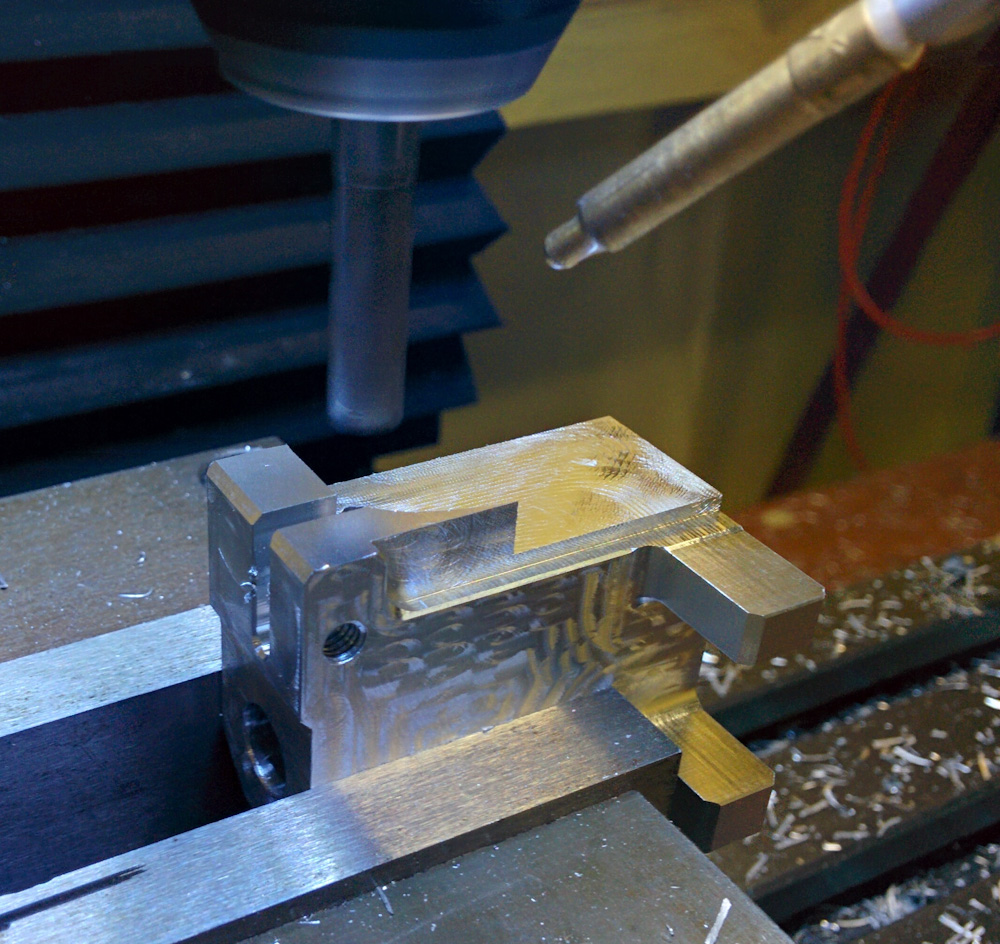
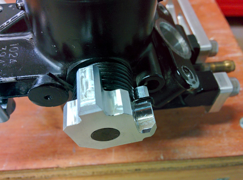
This is the almost-completed cylinder 4 link. The clamp on the left clamps to the throttle shaft, the two tabs on the right will make up the adjustment mechanism.
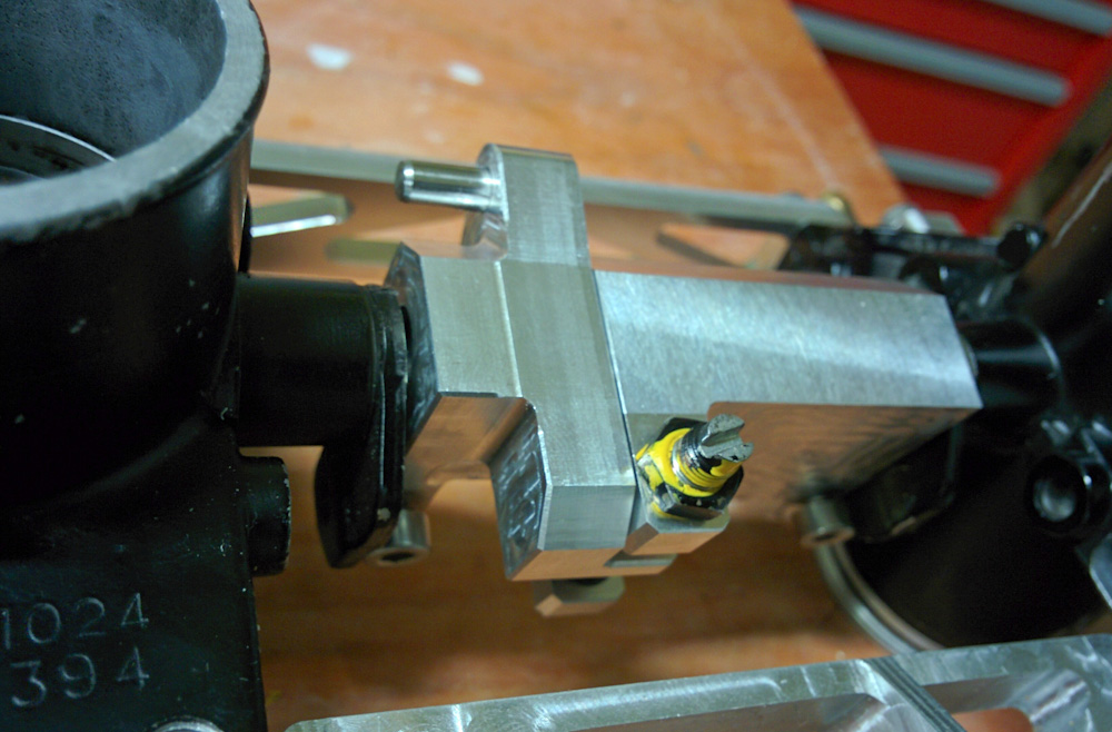
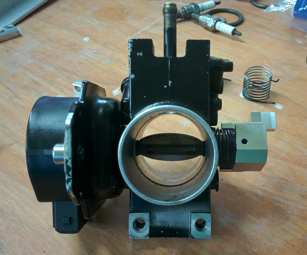
Here are the cylinder 2 & 4 throttle bodies with the linkage attached. The black and yellow screw is the M5x0.5 adjustment screw reused from the original GPz linkage. The 4mm dowel pin on the top is where the front-back link will ride.
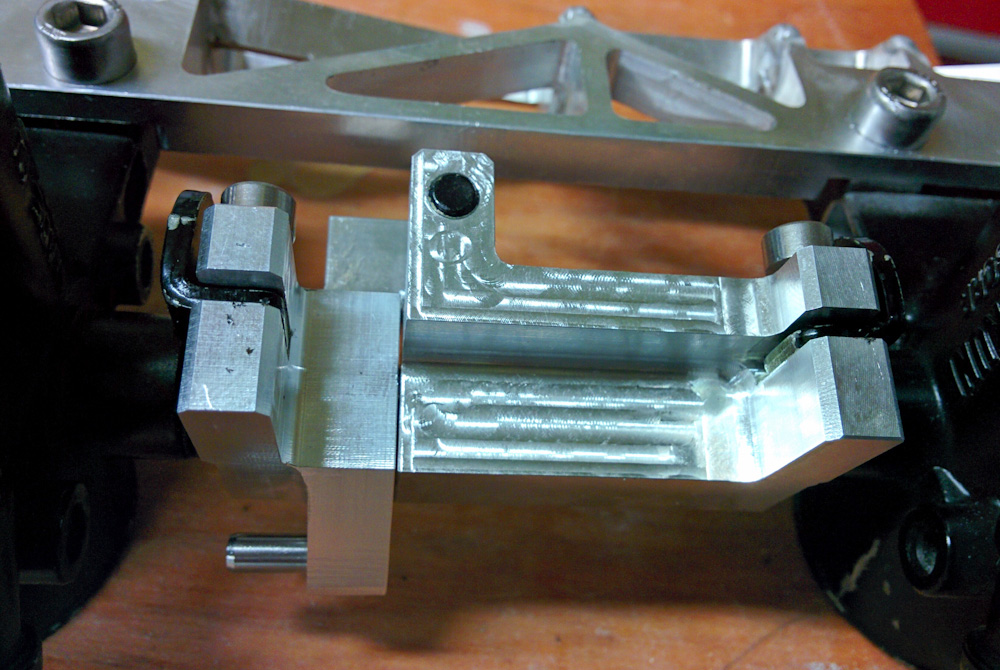
The opposite side of the cylinder 2/4 linkage. The tabs on the end clamp onto the throttle shafts.
The only problem is that I did not make the cutouts in the clamps that hold onto the throttle shafts deep enough, so the rotation axis of the linkage doesn’t quite line up with that of the throttles. This could be solved by recutting them a bit deeper, but I think it will be easier to simply grind off some material from the tabs on the throttle shafts.
So far so good. Now for the back cylinder parts. There are three of them, because both cylinders 1 & 3 need to be adjustable in relation to the link coming from the front cylinders. Setting up the CAM and fabricating these parts also went pretty smooth. Perhaps suspiciously so…
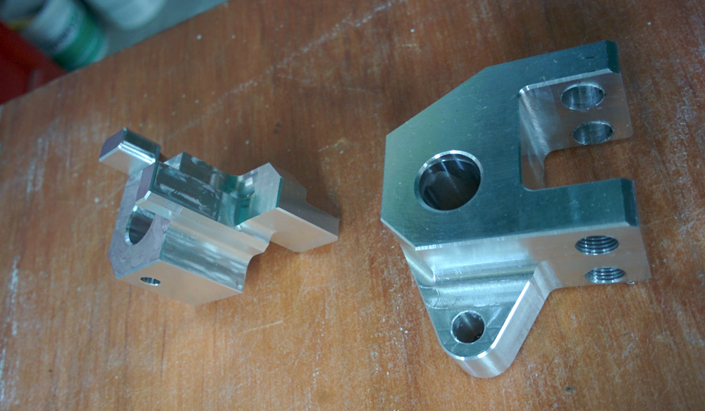
These are the cylinder 1, on the left, and center, right, parts. The threads on the center piece on the right are the adjustment tabs for the two cylinders.
These parts slide onto the throttle shafts and are locked in place with spring pins. Luckily the 7.98mm reamed hole fit snugly onto the shaft, but when I mounted the cylinder 1 link, I was dismayed to find…
The cylinder 1 link fit perfectly onto the shaft and held the return spring as designed. Unfortunately, it held the spring in the wrong direction… Rather than pulling the butterfly closed, it pulled it wide open!
Each throttle body has a return spring, which is held by tabs on the part. I had carefully measured these, but had somehow gotten them mirror flipped! This is kind of hard to keep track of on the CAD, because you always flip everything around, and the springs are on different sides of the different throttle bodies, meaning both directions are used. In hindsight, it’s perfectly obvious when moving the mechanism in Fusion that the spring holding tabs are backwards on this part.
Suffice to say I was frustrated. However, I realized that I could actually use this part. Cylinder 4 needs a spring holder on its shaft, but it’s on the outside so doesn’t need to connect to anything. And because it’s on the outside, its spring works in the correct direction for this part.
Relieved I could actually salvage something from this part, I went ahead and milled off everything outside the end of the throttle shaft. Then I quickly hand-typed some G-code to put some chamfers on the outside so it didn’t have such sharp edges. Doesn’t look half bad.
This is the cylinder 4 throttle body spring, held by the remnants of the incorrect part. It doesn’t even look that hacked up.
So that’s how things stand now. I need to correct the design for the cylinder 1 & 3 links, fabricate those, and finally the front-back link. It’s getting closer.
that is going to be a beautiful piece of machinery when assembled. great work.
Pingback: Microsquirting the NC30, part #39: More throttle linkage progress – Patrik's projects