Some of the rivets used to assemble the Sling are counter-sunk, that is, they have a flat head that is flush with the skin of the aircraft. This has the advantage of giving the aircraft a more smooth appearance and also improving the air flow over the surface. Having a smooth surface is most important on the leading edges of the wings and tail, and since countersunk rivets are less strong than their normal counterparts it’s only used where it matters.
In order for a countersunk rivet to fit, the parts naturally also have to have the corresponding shape. For thicker parts, like the spars, this can be done with a normal countersinking operation where you drill out a conical hole. Most of the parts in an airplane, however, are very thin. The skins and ribs, like in the picture above, are generally only 0.5mm thick, far too thin to countersink a hole. Instead, the sheet metal is deformed into a “dimple”, a cone where the rivet can rest.
Dimpling the metal is done with a “dimple die”, two hardened steel parts that are pressed together to form the dimple. This takes a significant amount of force, especially in the places where thicker 1mm sheets are used. You also have to be able to dimple holes in the middle of the wing skins, so whatever tool is used needs a fairly large opening.
The tool generally used for dimpling is the DRDT-2 from experimentalaero.com. This has a large C-frame and a hand-operated plunger. While you can buy the entire thing, the frame is very large and heavy and I neither wanted to pay for shipping it to Hawaii or fit it in the move. The alternative is to just buy the plunger and manufacture your own frame, so that’s what I was planning to do.
The first problem was figuring out where I could procure the quite large 150x75x5 rectangular steel tubing that’s required. I’m not familiar with any place selling steel for fabrication to private individuals here, so my Dad gave his old employer a call to see if he could figure it out. He used to work at Nordic Road Safety, which manufactures guardrails for roads. They told us to come by and happily told us we could take anything we could find in their storehouse. They had some 120x80x5, not quite as large as the original, but I figured it would work. Big Mahalos to Åke and Birger at NRS!
The tubing was at the absolute max of what my Rage 3 miter saw can cut, and by the end of it, the saw blade was almost unusably dull. It did work well, though, and I got the angles of the cuts almost perfect.
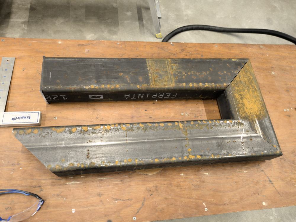
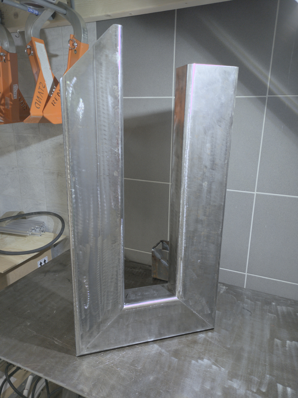
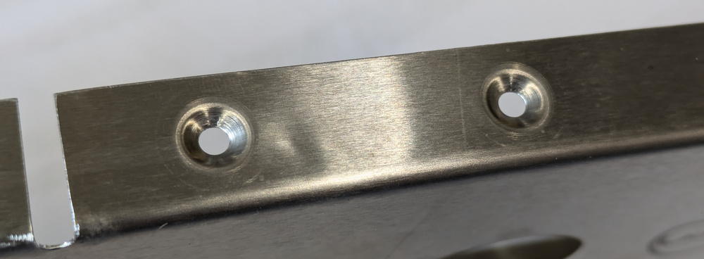
The dimpler frame is assembled from three pieces of tubing and a flat plate. The important thing here is to ensure that the flat plate in the upper left, where the plunger mounts, is exactly orthogonal to the tubing under it, where the other die will sit.
Now it was time to see how much my welding skills had atrophied, but the first hurdle was that argon bottles in Sweden have a totally different thread than my (quite nice) US regulator. I ended up replacing the part that attaches to the bottle, because that is threaded into the regulator with a simple 1/4″ NPT. The easiest solution was to buy the cheapest possible Swedish regulator and unscrew the bottle attachment tube. This of course does not attach to the regulator with a NPT thread (since NPT threads aren’t used in Europe) so I had to find an NPT die and re-cut the thread.
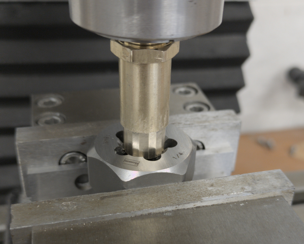
Cutting the thread in the brass tube that attaches to the Swedish Argon bottles. I first had to reduce the diameter of the tube a bit, and since I don’t have a lathe I milled an approximate circle consisting of 16 flats.
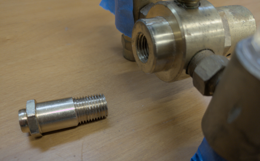
The bottle attachment ready for threading into the regulator.

The regulator with its new bottle attachment.
Since this connection is under full bottle pressure, which is 2500psi/170 bar, the fit has to be pretty good or you’ll lose a lot of expensive Argon. It actually turned out to be very tight, I can close the bottle valve and have the needle barely move in a day. Ok, ready to do some welding.
The parts tacked together.
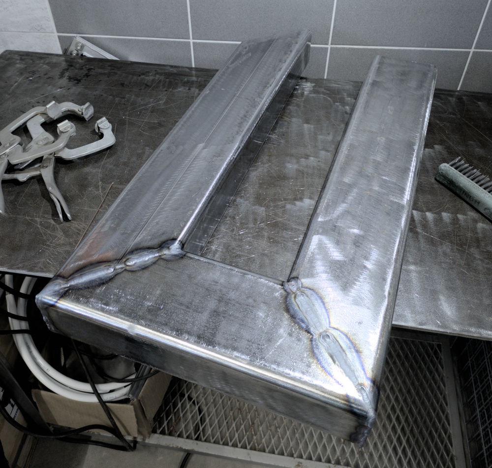
Frame welded together.
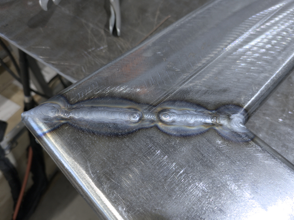
A close look at the welds.
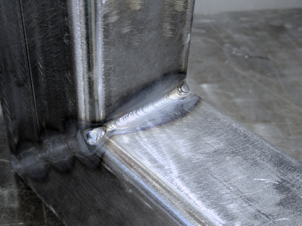
Even the inner corner weld looked ok. Usually I can’t manage anything close to that nice in aluminum.
When using the dimpling tool, it’s important it can be moved around and be placed around the work benches so the large skins can rest on the bench tops while you dimple them. To make this possible, I attached the same adjustable legs and retractable casters as on the workbenches.
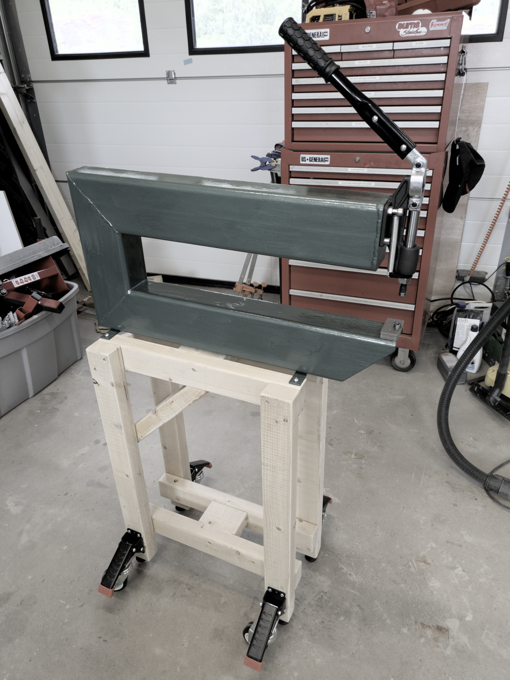
The assembled and painted dimpling tool on its stand. The stand is quite narrow but reasonably stable since the wheels are on the outside.
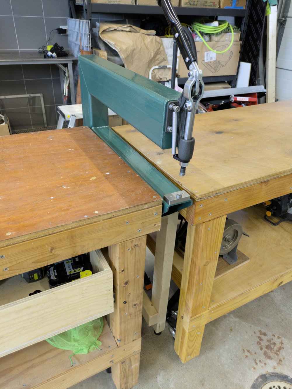
This is an example of how the tool fits in between the workbenches. If needed, it can also be placed further towards the front or back.
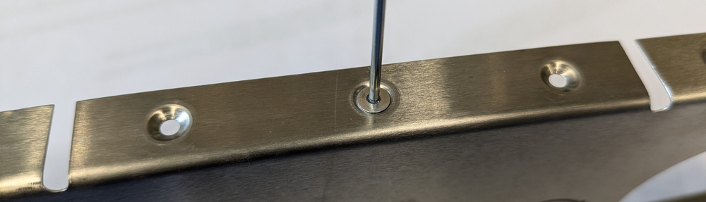
Once the tool was fully assembled, it was time for a test. The DRDT-2 instructions say you should have enough preload to see a witness mark from the entire die, not just a ring around the edge, or the hole will be underdimpled. When I tried this on a 1mm aluminum sheet, the preload required to get such a witness mark had the frame flexing 3mm when the handle bottomed out. Based on the preload recommendation for the DRDT-2 this is more flex than with the original frame, not surprising since the area moment of inertia of a 120×80 profile is about half of a 150×75 one. So the original frame should flex about 1.5mm. This is still well within requirements, and it yields some beautifully dimpled holes.
Some dimpled holes in one of the horizontal stabilizer ribs.
With the dimpling tool ready to go, it was time to start actually working on the empennage kit!
Pingback: Countersinking – Patrik's projects