The last post talked about dimpling, bending the sheet metal to fit a countersunk rivet. Its larger sibling is countersinking, which is used when the metal is too thick to allow dimpling.
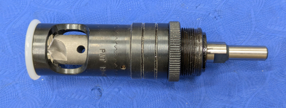
Countersinking is done with a countersinking tool, basically a drill with the correct angle and a pilot that holds it in the correct position in the hole. The tool is mounted in a cage which has two purposes: it makes it easier to hold the drill exactly perpendicular to the surface, and it has a stop that sets the depth of the countersink.
This of course begs the question: what is the correct depth?
If you’re just countersinking a hole to put a rivet directly in it, the answer is easy: countersink enough that the top of the rivet sits flush with the surface. However, this is a pointless rivet, since it won’t actually hold anything together. The typical situation is that we countersink a hole that will then be riveted to a dimpled, thin aluminum sheet, like a skin, above it. Now the geometry of the situation makes it a bit more complicated and less obvious.
If the hole is countersunk enough that the rivet head sits flush with the surface, and you then put a 0.5mm skin with a dimpled hole on top of it, the rivet will not sit flush with that surface. Because of the thickness of the skin, the back side of the dimpled hole has a bigger dimple than the front side, where the rivet sits, and the countersink has to be made deeper to account for this.

This sketch illustrates why the countersunk hole on the bottom needs to be larger than the dimpled hole in the overlying skin. T is the thickness of the skin and h the depth of the countersunk hole from the overlying dimple. The triangle in the upper left is a blow-up of the little triangle in the center of the drawing.
Using the triangle from the drawing above and a little trigonometry, it’s easy to figure out that the depth of the countersunk hole relative to the dimple in the top skin will be h=T/(sin α/2). The countersink angle α of the rivets used in the Sling kit is 120 degrees, which gives us h=1.15T. (This is different from that of “aircraft” solid rivets, 100 degrees, which would give h=1.3T.) If we use a hole where the rivet head sits flush, which is reasonably easy to set up, the excess depth over that is 0.15T (0.3T for aircraft rivets.)
For the typical 0.5mm thick skin, the extra depth is 0.075mm or 3 thousands of an inch. Not much, but significant. (The abhorrent unit is handy because the countersink cage can be set in steps of thousands of an inch, so this means an additional 3 steps over a rivet that sits flush. For the thicker 1mm metal used in some spars, we want 6 steps.)
I’m vindicated by the fact that Van’s Aircraft, which uses 100-degree rivets, specify a depth of 5-6 steps for their dimpled skins, which are also 0.5mm. 6 thousands of an inch is indeed what the formula above would predict.
Some people are under the assumption that you can find the correct countersink depth through trial and error by making sure that the dimpled skin sits flush when held against the countersunk part. This is not a good method because, in contrast to my drawing above, the dimpled hole does not have a sharp edge. The transition is somewhat rounded, so a hole large enough for the skin to sit flush will actually have a space between the two parts in the dimple itself. To not compromise rivet strength, it is essential that there be no voids between the parts where the rivet clamps them together, so over-sinking is worse than under-sinking.
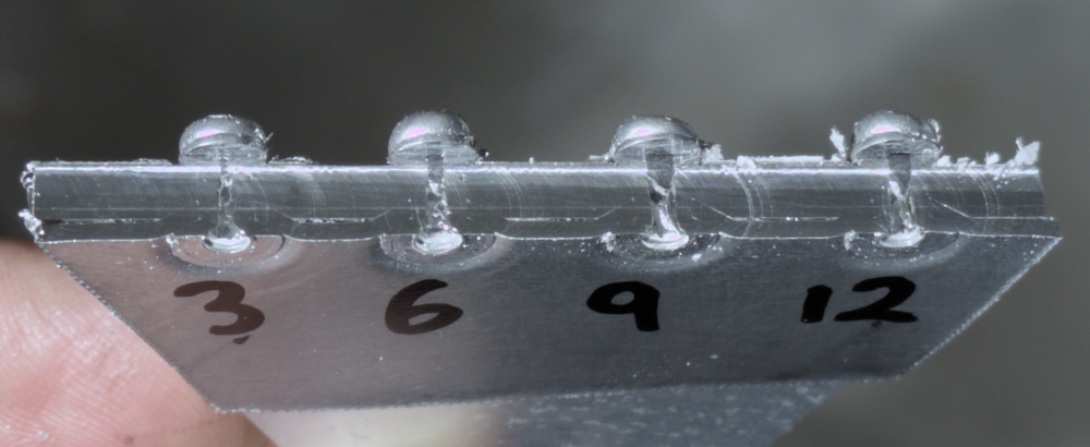
After doing this math I decided to test this in practice. I’d seen people cutting half-way into the rivet joint to inspect, so this seemed like a perfect time to fire up the CNC.

Cutaway view of four countersunk joints where a 1mm skin has been riveted to a thicker bottom. The numbers indicate the excess countersink depth in thousands of an inch. The 9 and 12 specimen show voids between the parts in the joint indicating a too deep countersink.
The metal gets smeared a bit by the cutter, so it’s not super easy to see, but this is 1mm thick material so the math above would predict a correct depth of 0.15mm or 6 countersink steps. That is indeed what I judged to be the best joint. The 9 is starting to show a bit of empty space between the parts in the joint, and the 12 clearly so. Staffan, my EAA inspector, independently picked the 6 as well, without being told about my expectations, so that’s what I went with when countersinking the horizontal stabilizer spar. (For 0.5mm skins, this is less crucial because it’s thin enough to at least partially be drawn together by the rivet.)
In the time between when this test was done and the post published, a substantial amount of actual airplane work has been completed. I’ll do a quick rundown next.