I was asked in a comment in the previous post to share the details of the antennas I made, so here we go.
The other antenna in the picture is the J-pole tuned for the 2m amateur band at 144-148MHz. I actually started out building one for the VHF aviation band at 115-135 MHz, based on K4ABT’s J-pole calculator. It worked OK, but not awesome. Then I got started modeling in EZNEC, and when I created this antenna as I had built it, I realized that a J-pole has way too narrow bandwidth to cover the aviation band. The tower at nearby Hilo airport is at 118MHz and since I had centered the antenna in the middle of the band at something like 126MHz, it did not do a very good job at all at 118.
So instead, I decided to repurpose it for the 2m amateur radio band, which is only 4MHz wide. Since going to a higher frequency would make it shorter, I could do that by just cutting the copper pipe and soldering new endcaps on it.
When I rescaled it to 146MHz in EZNEC, I of course had to keep the separation between the two sections the same as it was built, so the separation was about 0.5″ larger than indicated by that calculator. Most calculators also say that the length of the bottom section is irrelevant, but in EZNEC it did make a difference, so I added it at the existing length of 11″. The trick was now to tweak the lengths of the poles and the feed point location to get the antenna tuned to the 2m band.
Modeling the feed point in EZNEC is a bit tricky, by the way. Since the source is located near the bottom of the “J”, it makes a small current loop. This is explicitly mentioned as something to be careful with in the EZNEC documentation, so I played with the segment lengths to make sure the results were stable. An additional problem is that the NEC calculating engine can’t handle changing wire diameters, so I had to model the coax feed as a 1/2″ diameter conductor when in reality it’s more like 1mm. This probably introduces some error in the calculation, so ideally the feed point should be tweaked experimentally using an SWR meter, if I had one.
While I could get a good impedance match by moving the feed point, the radiation pattern was not ideal. The pattern was fairly strongly tilted upwards. However, I discovered that tweaking the relative lengths of the long and short sections would move the pattern up and down, as shown in the plot below.
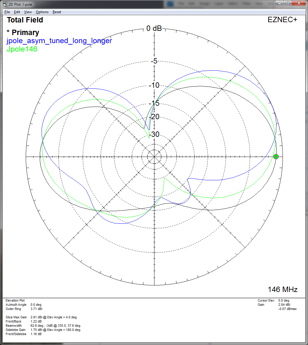
The radiation pattern of the J-pole. The original down-scaled antenna is shown in green as “Jpole146”. When I changed it to make the long section longer and the short section shorter (while keeping the minimum SWR at 146MHz) the pattern tilted upward as shown in blue. In contrast, when I shortened the long section and extended the short section, I arrived at the final result shown in black. While there is still a net tilt to the pattern, the maxima in both directions are now on the horizon.
So, by making the short section slightly longer and the long section shorter (where the exact ratio of the changes was determined by keeping the minimum SWR point in the center of the 2m band at 146MHz), and then tuning the feed point location again, I arrived at a design that has the maximum gain in the horizontal direction and is in resonance with a perfect impedance match at 146MHz, as shown below.
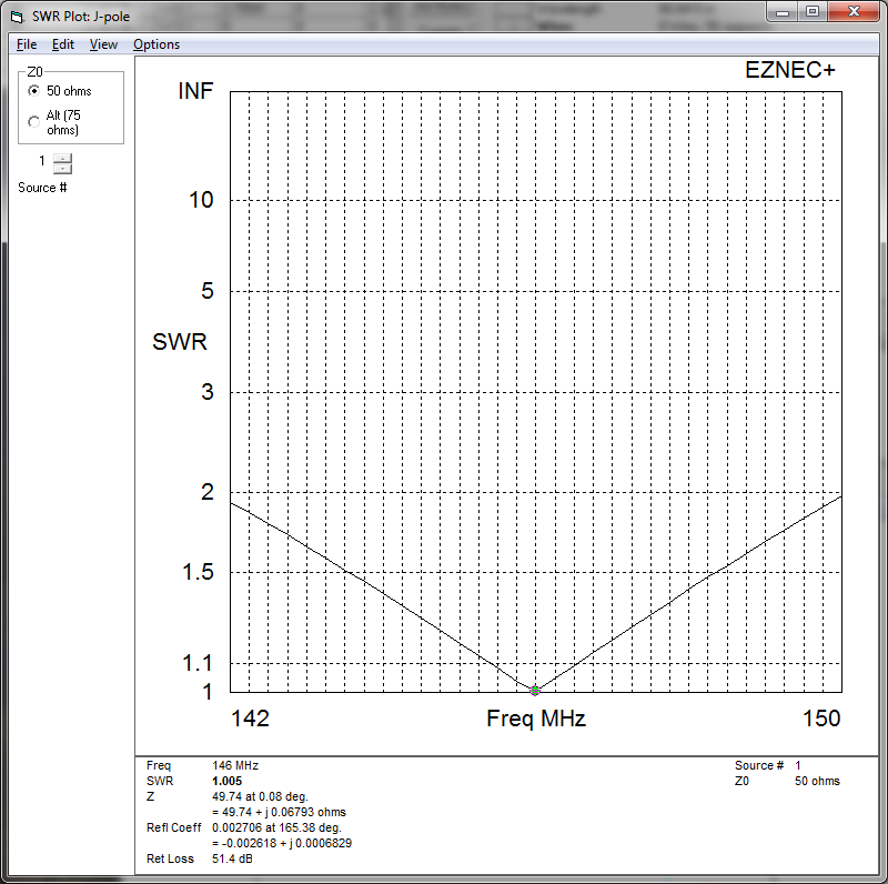
The SWR of the tuned J-pole. At 146MHz, the impedance is a practically perfect match to 50ohm cable, and across the entire band, the SWR is less than 1.4.
So, for those of you who want to go out and solder one up, here are the measurements: The long section (dimension A in the calculator) is 1450mm, the short section (dimension B) 519mm, the separation (dimension D) 59mm, the bottom section 280mm, and the feed point located 59mm away from the bottom. Note that unlike what’s mentioned on that site, these measurements are relative to the center of the conductors.
Again, I don’t have an SWR meter or a spectrum analyzer, so I can’t actually verify these numbers, but I can say that the Big Island Amateur Radio Club‘s repeater up in Kulani comes in crystal clear. Not that I’ve talked to anyone yet, but at least now I have an antenna that I can do it with, once I route the coax down from the attic.
Great! Thanks for sharing your valuable work.
Patrik, you never cease to amaze me. You are quite the builder, maintainer, inventor, and chronicler. From repairing motorcycles, building airplane parts, remodeling your house, protecting your house from water damage, and now building antennas for radio and airplane tracking. You not only do it but write about it in a way us non-technical/mechanical types can understand. Pretty AWESOME. Kennon